Multi-mode wind power plant

A multi-mode, power generation technology, applied in wind turbines, wind turbine combinations, and wind turbines at right angles to the wind direction, etc., can solve the problems of high hoisting costs, destroying birds with blades, and incomplete lightning protection facilities, so as to achieve the utilization of wind energy. High efficiency, small impact on the ecological environment, and easy operation and maintenance

Pending Publication Date: 2020-09-22
朱志刚
View PDF6 Cites 0 Cited by
  • Summary
  • Abstract
  • Description
  • Claims
  • Application Information

AI Technical Summary

Problems solved by technology

[0003] Under the condition of unstable wind speed, it is difficult for existing generator sets to be connected to the grid, and it is easy to abandon wind and electricity
The generator set weighs tens of tons and is installed at a height of nearly 100 meters. The center of gravity is too high, which poses a safety hazard. The lightning protection facilities are not complete and are prone to lightning strikes. The wind power tower uses too much material to achieve strength and is expensive.
Lifting costs are high
The maintenance cost is too high, and it is difficult to monitor and guarantee the generator set during operation;
[0004] In addition, the existing wind power blades have a long and narrow shape and a fast rotation speed. Because the blades rotate perpendicular to the ground, they occupy a large airspace area and produce translucent disturbance images that make it difficult for birds to identify and affect the migration of migratory birds. There have been incidents where blades have struck birds

Method used


Image

  • Multi-mode wind power plant
  • Multi-mode wind power plant
  • Multi-mode wind power plant

Examples


Embodiment 1

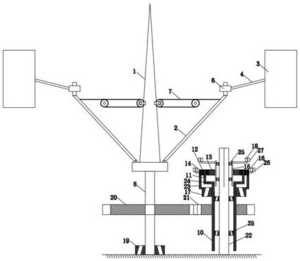
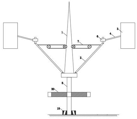
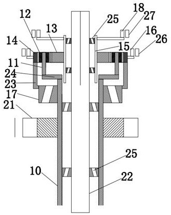
[0032] Such as figure 1 - As shown in 7, a multi-mode wind power station provided by an embodiment of the present invention includes a wind turbine, a transmission system, and a power generation group; the transmission system is used for power connection between the wind turbine and the power generation group;

[0033] special combination figure 1 , 2 , 4, 5, 6, 7, fan unit: including a rotating support body 1, the rotating support body 1 is a tower, a lightning rod is arranged above the tower to prevent lightning strikes, and the tower is uniformly arrayed with several blades along the circumferential direction Trusses 2, the ends of each blade truss 2 are provided with outwardly protruding blades 3, the blade trusses 2 are symmetrically arranged in pairs, and the blades 3 are connected to the ends of the blade trusses 2 through blade connecting rods 4 in rotation, The blade truss 2 is provided with a stopper 5, and the stopper 5 is used to block the blade connecting rod 4;...


PUM


Abstract

The invention belongs to the technical field of wind power generation, and particularly relates to a multi-mode wind power plant. The multi-mode wind power plant comprises a wind turbine group, a transmission system and a power generation group; the transmission system is used for power connection between the wind turbine group and the power generation group; and the wind turbine group comprises arotating support body, wherein a plurality of blade trusses are uniformly arrayed in the circumferential direction of the rotating support body, blades protruding extending outwards are arranged at the tail end of each blade truss, the blades are rotatably connected to the tail ends of the blade trusses through blade connecting rods, a blocking piece is arranged on each blade truss, and the blocking piece is used for blocking the corresponding blade connecting rod. According to the wind power plant, the manufacture cost is low, the wind energy utilization efficiency is high, the influence onthe ecological environment is small, site selection is convenient, and operation and maintenance are facilitated.

Description

technical field [0001] The invention belongs to the technical field of wind power generation, and in particular relates to a multi-mode wind power station. [0002] technical background [0003] Under the condition of unstable wind speed, the existing generator sets are difficult to connect to the grid, and it is easy to abandon wind and electricity. The generator set weighs tens of tons and is installed at a height of nearly 100 meters. The center of gravity is too high, which poses safety hazards. The lightning protection facilities are not complete and are prone to lightning strikes. The wind power tower uses too much material to achieve strength and is expensive. Lifting costs are high. The maintenance cost is too high, and it is difficult to monitor and guarantee the generator set during operation; [0004] In addition, the existing wind power blades have a long and narrow shape and a fast rotation speed. Because the blades rotate perpendicular to the ground, they occu...

Claims


Application Information

Patent Timeline
Patent Type & Authority Applications(China)
IPC IPC(8): F03D3/06F03D9/25F03D80/00
CPCF03D3/067F03D9/25F03D80/00Y02E10/74Y02P70/50
Inventor 朱志刚朱希蕾毛浩远孙凯军毛应民荣宗信张天歌庞涛刘宇于立军孟强张生华袁帅董志军徐晓辉
Owner 朱志刚
Why Eureka
Try Eureka