
Butterfly spherical valve

A spherical valve, butterfly technology, applied in the direction of lift valve, valve detail, valve device, etc., can solve the problem of sealing performance degradation, achieve the effect of improving wear resistance, strengthening wear cycle, and improving sealing performance

Inactive Publication Date: 2020-09-22
SICHUAN FLUOWAY FLUID CONTROL EQUIP CO LTD
View PDF7 Cites 0 Cited by
  • Summary
  • Abstract
  • Description
  • Claims
  • Application Information

AI Technical Summary

Problems solved by technology

[0003] The sealing principle of the butterfly valve in the prior art when it is closed is: when the valve is closed, through the rotation of the valve plate, the outer circular sealing surface of the valve plate squeezes the sealing ring of the valve seat, so that the valve seat generates elastic force as the sealing specific pressure to ensure The sealing of the valve, but in the process of continuous closing of the valve plate in the prior art, it rubs against the sealing ring of the valve seat for many times. Under mechanical wear, it is easy to cause the sealing performance between the two sealing surfaces to decline. It exists: the valve seat The technical problem that is likely to cause the sealing performance to decline after mechanical wear and tear

Method used


Image

  • Butterfly spherical valve
  • Butterfly spherical valve
  • Butterfly spherical valve

Examples


Embodiment Construction

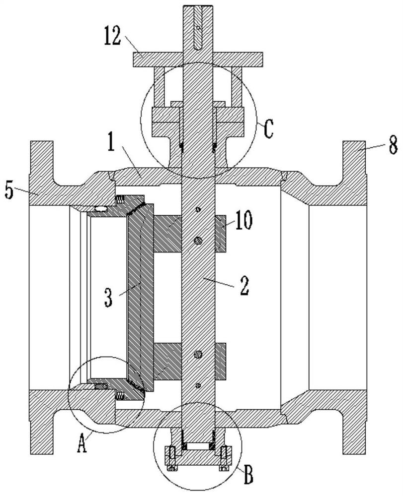
[0028] The following will be combined with Figure 1-5 The technical solutions of the present invention are clearly and completely described, and obviously, the described embodiments are part of the embodiments of the present invention, but not all of them. Based on the embodiments of the present invention, all other embodiments obtained by persons of ordinary skill in the art without making creative efforts belong to the protection scope of the present invention.

[0029] In the description of the present invention, it should be understood that the orientation or positional relationship indicated by the terms "upper", "lower", "front", "rear", "inner", "outer" etc. Orientation or positional relationship is only for the convenience of describing the present invention and simplifying the description, and does not indicate or imply that the referred device or element must have a specific orientation, be constructed and operated in a specific orientation, and thus should not be c...


PUM


Abstract

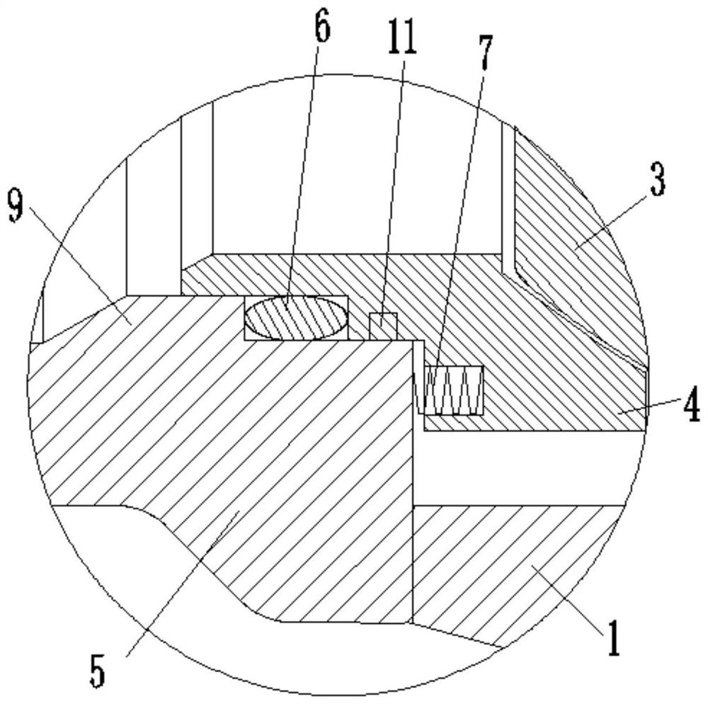
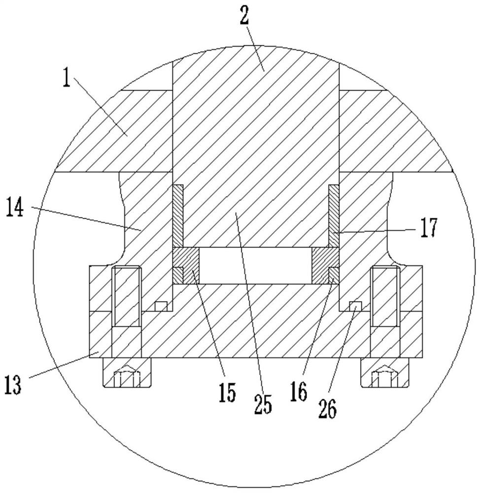
The invention discloses a butterfly spherical valve, and relates to the field of butterfly valves. The butterfly spherical valve comprises a valve body, a valve shaft, a spherical disc plate, a valveseat, an inlet flange body, a sealing ring and an elastic part. The inlet flange body is fixedly connected with one side of the valve body, the valve shaft is rotationally connected with the valve body, the spherical disc plate is arranged inside the valve body, one side of the spherical butterfly plate is connected with the valve shaft, the outer side face of the valve seat is of a step structure, the step structure sequentially comprises a first step, a second step and a third step towards the direction far away from the spherical disc plate, the inner side surface, close to the valve seat,of the inlet flange body is provided with a convex part, the outer side surface of the third step abuts against the inner side surface of the convex part, the outer side surface of the second step abuts against the inner side surface of the valve seat, and the sealing ring is arranged between the second step and the convex part. The technical problems in the prior art are solved, and low sealing performance easily caused by the mechanical wear of the valve seat is avoided.

Description

technical field [0001] The invention relates to the field of butterfly valves, in particular to a butterfly spherical surface valve. Background technique [0002] Butterfly valve, also known as flap valve, is a regulating valve with simple structure, which can be used for switch control of low-pressure pipeline medium. A valve that can be used to control the flow of various types of fluids such as air, water, steam, various corrosive media, mud, oil, liquid metal and radioactive media. It mainly plays the role of cutting and throttling on the pipeline. The opening and closing part of the butterfly valve is a disc-shaped butterfly plate that rotates around its own axis in the valve body to achieve the purpose of opening and closing or adjustment. [0003] The sealing principle of the butterfly valve in the prior art when it is closed is: when the valve is closed, through the rotation of the valve plate, the outer circular sealing surface of the valve plate squeezes the seal...

Claims


Application Information

Patent Timeline
Patent Type & Authority Applications(China)
IPC IPC(8): F16K1/20F16K1/42F16K25/00F16K27/02F16K27/08F16K41/02
CPCF16K1/2014F16K1/2028F16K1/2057F16K1/2078F16K1/2085F16K1/42F16K25/005F16K27/0227F16K27/08F16K41/026
Inventor 刘全
Owner SICHUAN FLUOWAY FLUID CONTROL EQUIP CO LTD
Learn More