
Fire extinguisher valve with limiting assembly

A technology of limit components and fire extinguishers, which is applied in the direction of valve details, control valves, valve devices, etc., can solve problems such as delay in fire extinguishment, time-consuming, property loss, etc., to prevent object leakage, prevent accidental spraying, and ensure The effect of quick use

Active Publication Date: 2020-09-22
YANCHENG OURUN PETROCHEMICAL EQUIP MFG CO LTD
View PDF6 Cites 3 Cited by
  • Summary
  • Abstract
  • Description
  • Claims
  • Application Information

AI Technical Summary

Problems solved by technology

[0003] The valve that controls the ejection of the fire extinguishing material inside the fire extinguisher bottle is generally fixed with a pin shaft to limit and fix the pressing component when it is not in use, so as to prevent accidental ejection, but when in use, the plastic ring needs to be removed first , and then pull out the pin shaft, the operation is more cumbersome, you may be in a panic, you need to spend time on extracting the pin shaft, it may delay the elimination of the fire, and may cause greater property damage, and you need to use it after pressing Pressing the hand all the time, time-consuming and labor-intensive

Method used


Image

  • Fire extinguisher valve with limiting assembly
  • Fire extinguisher valve with limiting assembly
  • Fire extinguisher valve with limiting assembly

Examples


Embodiment Construction

[0024] In order to make the technical means, creative features, goals and effects achieved by the present invention easy to understand, the present invention will be further described below in conjunction with specific embodiments.

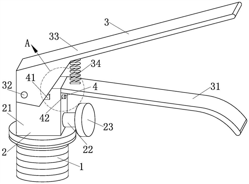
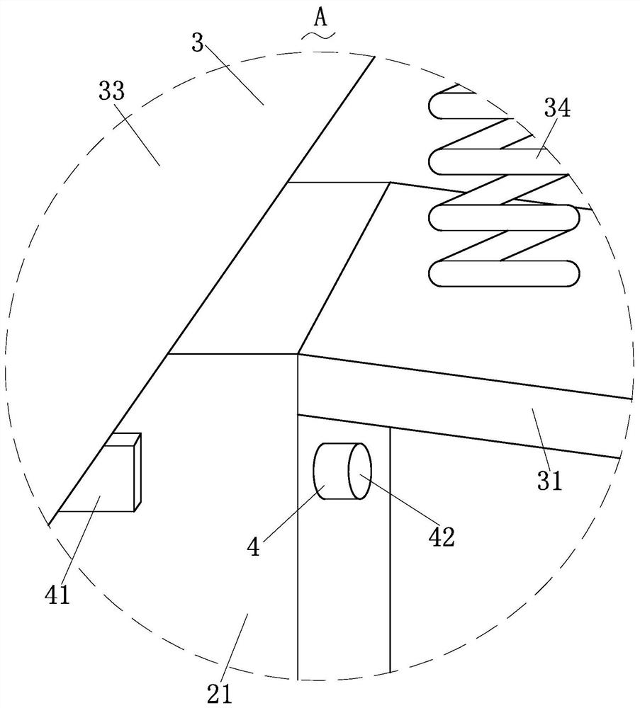
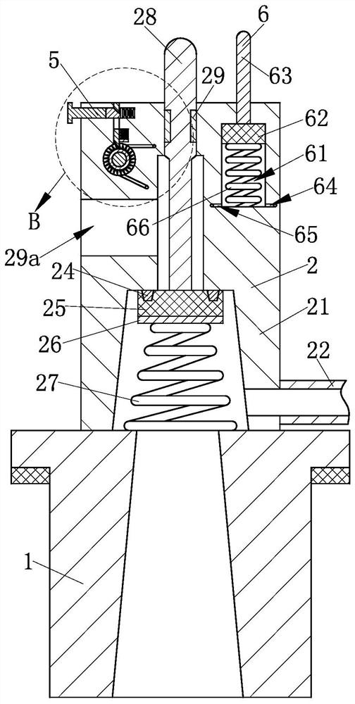
[0025] Such as Figure 1-Figure 6 As shown, a fire extinguisher valve with a limiting assembly according to the present invention includes a mounting sleeve 1, a valve body structure 2, a pressing structure 3, a limiting structure 4, a positioning structure 5 and a lubricating structure 6, which are used to One end of the installation sleeve 1 where the valve is connected to the fire extinguisher bottle is installed with the valve body structure 2 for controlling the on-off of objects inside the fire extinguisher bottle, and one end of the valve body structure 2 is installed for pressing control. The pressing structure 3 for the on-off function of the valve body structure 2; the limiting structure 4 for limiting the pressing structure 3 is installed...


PUM


Abstract

The invention relates to the technical field of fire extinguisher valves, in particular to a fire extinguisher valve with a limiting assembly. The fire extinguisher valve comprises a mounting sleeve,a valve body structure, a pressing structure, a limiting structure, a positioning structure and a lubricating structure. Through the arrangement of the limiting structure, not only the pressing structure can be limited thereby preventing ejection caused by false touch, the assembly for limiting the pressing structure can be rapidly contracted when the pressing structure is needed to be used so that the rapid use of the pressing structure can be ensured; through the arrangement of the positioning structure, the effect of fire extinguishing can still be achieved without the need of pressing allthe time after the pressing structure is pressed, and the size of required ejection can be adjusted according to the actual condition so that better targeted fire extinguishing can be achieved, and the better fire extinguishing effect can be achieved; and the pressing structure can also act on the lubricating structure while working, the work of the lubricating structure can perform oiling and lubricating work on the positioning structure, and therefore the effect of lubricating a rotary part during pressing can be realized, and the situation of laborious rotating is avoided.

Description

technical field [0001] The invention relates to the technical field of fire extinguisher valves, in particular to a fire extinguisher valve with a limiting component. Background technique [0002] A fire extinguisher is a portable fire extinguishing tool. Chemicals are placed in the fire extinguisher to put out the fire. Fire extinguishers are one of the common fire prevention facilities. They are stored in public places or places where fires may occur. Different types of fire extinguishers contain different ingredients and are specially designed for different fire causes. Care must be taken during use to avoid adverse effects and danger. Valves are pipeline accessories used to open and close pipelines, control flow direction, adjust and control the parameters (temperature, pressure and flow) of the conveying medium. According to its function, it can be divided into shut-off valve, check valve, regulating valve and so on. The valve is a control component in the fluid del...

Claims


Application Information

Patent Timeline
Patent Type & Authority Applications(China)
IPC IPC(8): F16K15/18F16K15/03F16K27/02F16K31/60F16K35/06F16N3/06F16N19/00A62C13/64
CPCA62C13/64F16K15/033F16K27/0209F16K31/602F16K35/06F16N3/06F16N19/00F16K15/1821
Inventor 不公告发明人
Owner YANCHENG OURUN PETROCHEMICAL EQUIP MFG CO LTD
Learn More