
Variable grating micro-signal separation device and manufacturing method thereof

A separation device and micro-signal technology, which is applied in the direction of measuring devices, particle size analysis, and analysis materials, etc., can solve the problems that affect the accurate judgment of signals, the difficulty of the process, and the inconvenience of implementation, so as to avoid superposition, control the process, and improve accuracy. Effect

Pending Publication Date: 2020-09-22
MEDCAPTAIN MEDICAL TECH
View PDF9 Cites 0 Cited by
  • Summary
  • Abstract
  • Description
  • Claims
  • Application Information

AI Technical Summary

Problems solved by technology

[0002] When detecting biological samples, the signal receiver will receive signals generated by multiple sample particles or gene fragments flowing through the capillary at the same time, and these signal intensities will be superimposed, thus affecting the accurate judgment of the signal
At present, there have been studies to solve this problem by means of chips. By making small flow channels for placing sample particles or gene fragments on the chip, in order to achieve the purpose of individual detection of sample particles and gene fragments, but This method is difficult to process and inconvenient to implement

Method used


Image

  • Variable grating micro-signal separation device and manufacturing method thereof
  • Variable grating micro-signal separation device and manufacturing method thereof
  • Variable grating micro-signal separation device and manufacturing method thereof

Examples


Embodiment Construction

[0021] Below in conjunction with embodiment and attached Figures 1 to 4 The present invention is further described.

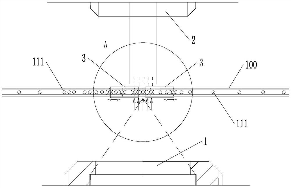
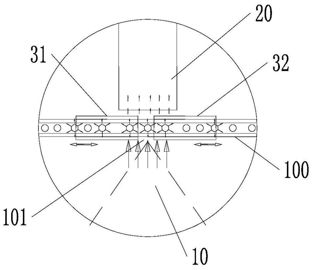
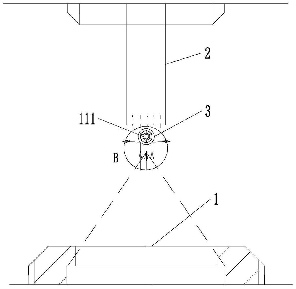
[0022] A variable grating micro-signal separation device, such as figure 1 As shown, it includes a capillary 100, an excitation light source 1 and a signal receiver 2, the capillary 100 is located between the excitation light source 1 and the signal receiver 2, an excitation light source 1 is arranged on one side of the capillary 100, and the excitation The emitting head 10 of the light source 1 is used to emit excitation light, and the emitted excitation light passes through the transparent capillary 100 and hits the substance to be detected 111 flowing through the capillary 100. The substance to be detected 111 is a sample particle or a gene fragment, and the Composed of several particles or gene fragments, the fluorescent signal emitted by them penetrates the transparent capillary 100 again and enters the signal receiver 2 on the other side of the capillar...


PUM


Abstract

The invention discloses a variable grating micro-signal separation device and a manufacturing method thereof. The separation device comprises a capillary tube, an excitation light source and a signalreceiver. The capillary tube is located between the excitation light source and the signal receiver, a grating sleeve is arranged on the outer surface of the capillary tube, and the grating sleeve ismade of a light absorption material. The number of the grating sleeves is two, the grating sleeves are respectively a first grating sleeve and a second grating sleeve, a gap is formed between the first grating sleeve and the second grating sleeve, and the width of the gap is greater than or equal to the size of a single to-be-detected substance particle in a capillary tube and is smaller than thesizes of two to-be-detected substance particles. One end, far away from the gap, of each of the first grating sleeve and the second grating sleeve extends out of an area covered by the light receivinglens on the capillary tube. The manufacturing method of the separating device is characterized in that a gap is formed between the first grating sleeve and the second grating sleeve by means of a gapgenerator. According to the invention, superposition of signals in a to-be-detected sample can be effectively reduced, and the detection accuracy is improved.

Description

technical field [0001] The invention relates to the field of bioengineering sample detection, in particular to a variable grating micro-signal separation device and a manufacturing method thereof. Background technique [0002] When detecting biological samples, the signal receiver will simultaneously receive signals generated by multiple sample particles or gene fragments flowing through the capillary at one time, and the signal intensities will be superimposed, thus affecting the accurate judgment of the signals. At present, there have been studies to solve this problem by means of chips. By making small flow channels for placing sample particles or gene fragments on the chip, in order to achieve the purpose of individual detection of sample particles and gene fragments, but This method is difficult in technology and inconvenient to implement. Therefore, it is necessary to develop other devices and methods capable of separating the signal of individual sample particles. ...

Claims


Application Information

Patent Timeline
Patent Type & Authority Applications(China)
IPC IPC(8): G01N15/02
CPCG01N15/0205
Inventor 吕才树
Owner MEDCAPTAIN MEDICAL TECH
Learn More