
Fuel delivery device

A technology of oil transportation and fuel oil, applied in the direction of power plant, transportation and packaging, charging system, etc., can solve the problems of high manufacturing cost and special structure, and achieve the effect of simple structure

Inactive Publication Date: 2003-08-06
ROBERT BOSCH GMBH
View PDF1 Cites 0 Cited by
  • Summary
  • Abstract
  • Description
  • Claims
  • Application Information

AI Technical Summary

Problems solved by technology

Disadvantages in oil delivery devices of this construction are that the container with the integrated suction jet pump requires high manufacturing costs and a special construction

Method used


Image

  • Fuel delivery device
  • Fuel delivery device
  • Fuel delivery device

Examples


Embodiment Construction

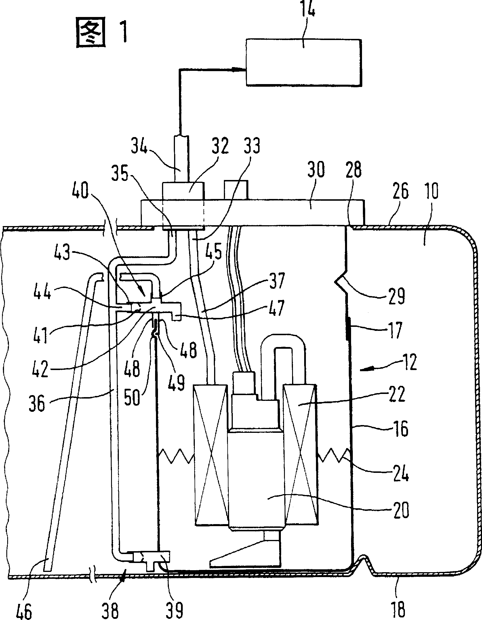
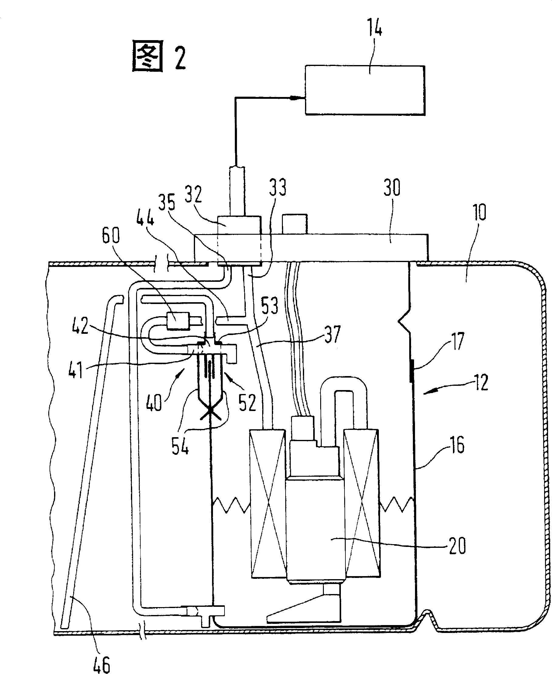
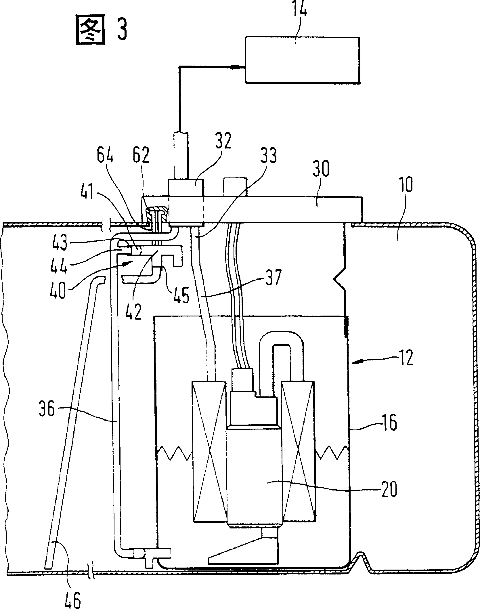
[0014] FIGS. 1 to 3 partially show a fuel reserve tank 10 of a motor vehicle, in which a delivery device 12 for feeding fuel from the reserve tank 10 to a fuel injection system of an internal combustion engine 14 of the motor vehicle is installed. The oil delivery device 12 has a pot-shaped container 16 which can be placed on the bottom 18 of the reserve oil tank 10 and fastened to the bottom 18 in a manner not shown. The container 16 can be made, for example, of oil-resistant plastic and is open at its upper end. A fuel delivery unit 20 is inserted into the container 16 , from which fuel is sucked in during operation of the unit and delivered to the internal combustion engine 14 . The fuel delivery unit 20 has a pump part and a motor part that drives it, in particular a drive motor. Furthermore, a filter 22 can be installed in the container 16 , by which the fuel delivered by the delivery unit 20 is filtered before it is delivered to the internal combustion engine 14 . The ...


PUM


Abstract

The fuel delivery device (12) has a receptacle (16) arranged in a storage tank (10) and a delivery unit (20) delivering fuel from the receptacle (16) to the internal combustion engine (14) of a motor vehicle. Further, there is provided at least one suction jet pump (40) which delivers fuel from the storage tank (10) into the receptacle (16). The suction jet pump (40) is fastened to an upper edge area (17) of the receptacle (16) as a separate constructional unit. The suction jet pump (40) is formed by a constructional unit having a propelling nozzle (41), a connection (43) for a propelling line (44), which connection (43) opens into the propelling nozzle (41), a mixing pipe (42) following the propelling nozzle (41), and a connection (45) for a suction line (46), which connection (45) opens into the mixing pipe (42). Two walls (48) located at a distance from one another project downward from the constructional unit (40), and the constructional unit (40) is mounted on the edge (17) of the receptacle (16) from the top, wherein the edge (17) of the receptacle (16) is introduced between the two walls (48). The suction line (46) connected to the suction jet pump (40) opens into the storage tank (10) remote of the receptacle (16).

Description

technical field [0001] The invention relates to an oil conveying device. Background technique [0002] Such an oil delivery device is known from DE 42 19 516 A1. This fuel delivery device is used to deliver the fuel in the spare fuel tank to the internal combustion engine of the motor vehicle. A container is installed in the reserve fuel tank, from which the fuel transfer unit delivers fuel to the internal combustion engine. Several suction injection pumps are integrated in the container, and the fuel in the spare fuel tank is delivered to the container by means of these injection pumps. Connected to these suction jet pumps are several suction lines that lead to various locations in the reserve tank. It can thus be ensured that the container can still be reliably filled with fuel when the reserve tank is relatively empty and if, for example, the fuel distribution in the reserve tank is uneven due to driving on a slope or a curve. The disadvantage of a fuel delivery dev...

Claims


Application Information

Patent Timeline
Patent Type & Authority Patents(China)
IPC IPC(8): B60K15/03B60K15/077F02M37/18F04F5/54
CPCB60K2015/03105B60K2015/03236B60K15/077B60K2015/03467Y10T137/2917
Inventor 斯蒂芬·克莱普纳库尔特·弗兰克斯特芬·米哈奇克劳斯-迪特尔·胡夫纳格尔京特-保罗·巴利耶阿尔贝特·格哈德格哈德·尧赫
Owner ROBERT BOSCH GMBH
Learn More