A mold stamping part with a safety protection component and its working method

A technology for safety protection and stamping parts, applied in the field of stamping dies, can solve the problems of increasing user operation steps, reducing flexibility, and reducing the safety of stamping parts of the die, so as to avoid left and right tilt, improve flexibility, and increase stability. Effect

Active Publication Date: 2022-04-22
德州豪沃机械制造有限公司
View PDF7 Cites 0 Cited by
  • Summary
  • Abstract
  • Description
  • Claims
  • Application Information

AI Technical Summary

Problems solved by technology

[0004] The existing die stamping parts with safety protection components have certain disadvantages in the use process. The traditional die stamping parts with safety protection components adopt an integrated fixed structure design, so that users can adjust the shape of die stamping parts In the structure, it is necessary to replace the parts, which increases the user's operation steps and reduces the flexibility of its use; secondly, the traditional die stamping parts do not have a safety protection structure, which reduces the safety of the die stamping parts in use. Safety, it is impossible to control its strength during the stamping process; at the same time, the traditional mold stamping parts do not have an auxiliary demoulding structure. When the traditional mold stamping parts complete the stamping process, the user needs to manually remove the stamped metal raw material Thereby increasing the user's operation steps, bringing certain adverse effects to the user

Method used


Image

  • A mold stamping part with a safety protection component and its working method
  • A mold stamping part with a safety protection component and its working method
  • A mold stamping part with a safety protection component and its working method

Examples


Embodiment Construction

[0033] The technical solutions in the embodiments of the present invention will be clearly and completely described below in conjunction with the embodiments of the present invention. Apparently, the described embodiments are only some of the embodiments of the present invention, not all of them. Based on the embodiments of the present invention, all other embodiments obtained by persons of ordinary skill in the art without creative efforts fall within the protection scope of the present invention.

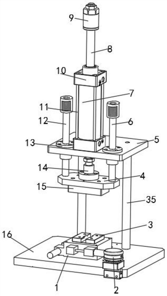
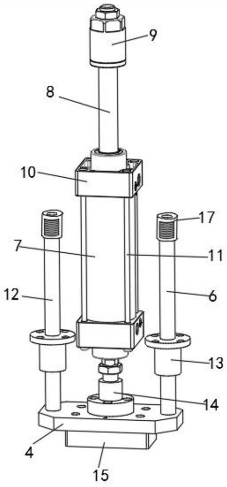
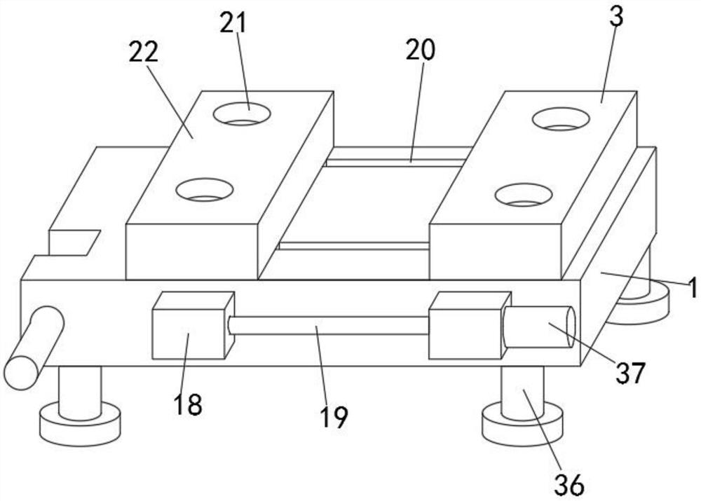
[0034] Such as Figure 1-6 As shown, a mold stamping part with a safety protection component includes a stamping base 1, a fixed top plate 5, a stamping top plate 4, a protective component 17, a stamping box 15 and a fixed bottom plate 16, and the stamping base 1 is fixed on the fixed bottom plate 16. On the outer surface of the upper end, two sets of moving chutes 20 are provided on the inner side of the upper end of the stamping base 1, and a stamping slider 22 is movably instal...


PUM


Abstract

The invention discloses a mold stamping part with a safety protection component, which includes a stamping base, a fixed top plate, a stamping top plate, a protection component and a stamping box. The stamping base is fixedly installed on the outer surface of the upper end of the fixed bottom plate. There are two sets of moving chute on the inner side of the upper end, the outer surface of the upper end of the fixed bottom plate is movably installed with a stamping slider, and the outer surface of the upper end of the fixed bottom plate close to the side of the stamping slider is fixedly installed with a stamping block, the stamping block There are two sets of stamping grooves on the inner side of the upper part of the stamping slider. The inner surface of the bottom of the stamping slider is movably installed with the first caster, and the inner surface of the bottom of the stamping slider is movably installed on the side close to the first caster. The second caster: a mold stamping part with a safety protection component in the present invention, so that the mold stamping part has a movable adjustment structure, which improves its flexibility in use, and at the same time makes it have an auxiliary demoulding structure, so that it can be used and operated more convenient.

Description

technical field [0001] The invention belongs to the technical field of punching dies, in particular to a die stamping part with a safety protection component and a working method thereof. Background technique [0002] The mold stamping part with safety protection components is a kind of mold stamping part that uses stamping method to stamp metal raw materials. The stamping die is to process metal or non-metal into parts or semi-finished products in cold stamping process. A special craft equipment. [0003] A multi-channel stamping die disclosed in comparative document CN103447413B is composed of stamping dies installed on successively arranged stations. Each stamping die is composed of a punch 10, a die 8 and a ejector device 9. The subsequent stamping die The top of the ejecting device is stepped. The elevation difference between the two sides of the step is greater than the thickness of the sheet 1. The range of the middle and lower faces of the step is larger than the ra...

Claims


Application Information

Patent Timeline
Patent Type & Authority Patents(China)
IPC IPC(8): B21D37/12B21D45/08B21D22/02B21D55/00
CPCB21D37/12B21D45/08B21D22/02B21D55/00
Inventor 王爱银
Owner 德州豪沃机械制造有限公司
Why Eureka
Try Eureka