Floating type numerical control rotary table safety locking structure

A CNC turntable and safety locking technology, which is used in large fixed members, metal processing mechanical parts, metal processing equipment, etc., can solve the accuracy of the rotary axis, the difficulty of manufacturing thin brake pads, the permanent deformation of the brake pads, and the abnormal friction and noise. problem, to achieve the effect of rapid braking, no influence on the accuracy of the turntable, and large braking force

CN111702511APending Publication Date: 2020-09-25宝鸡忠诚机床股份有限公司
0 Cites 0 Cited by

Patent Information

Authority / Receiving Office
CN · China
Patent Type
Applications(China)
Current Assignee / Owner
Publication Date
2020-09-25

Smart Images

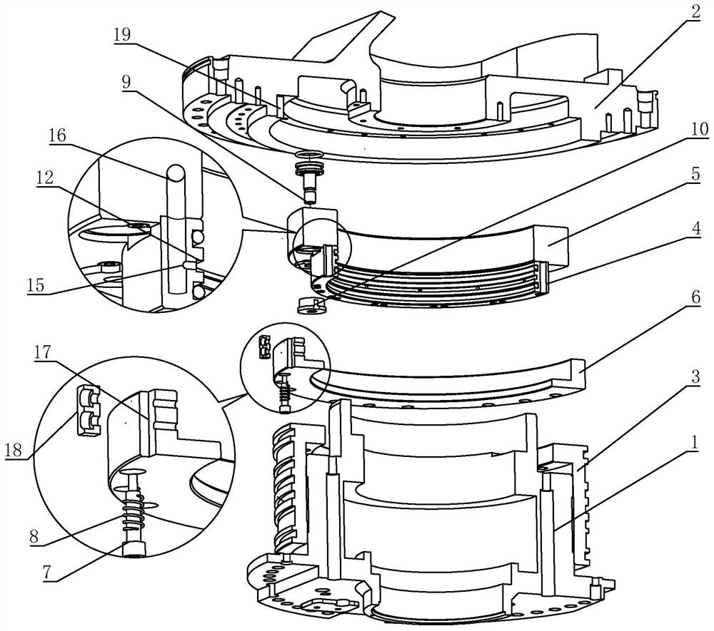
  • Figure 1
    Figure 1
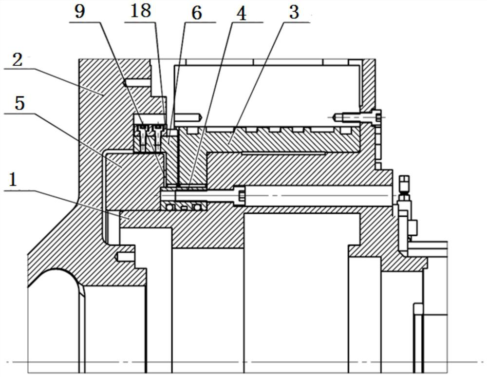
  • Figure 2
    Figure 2
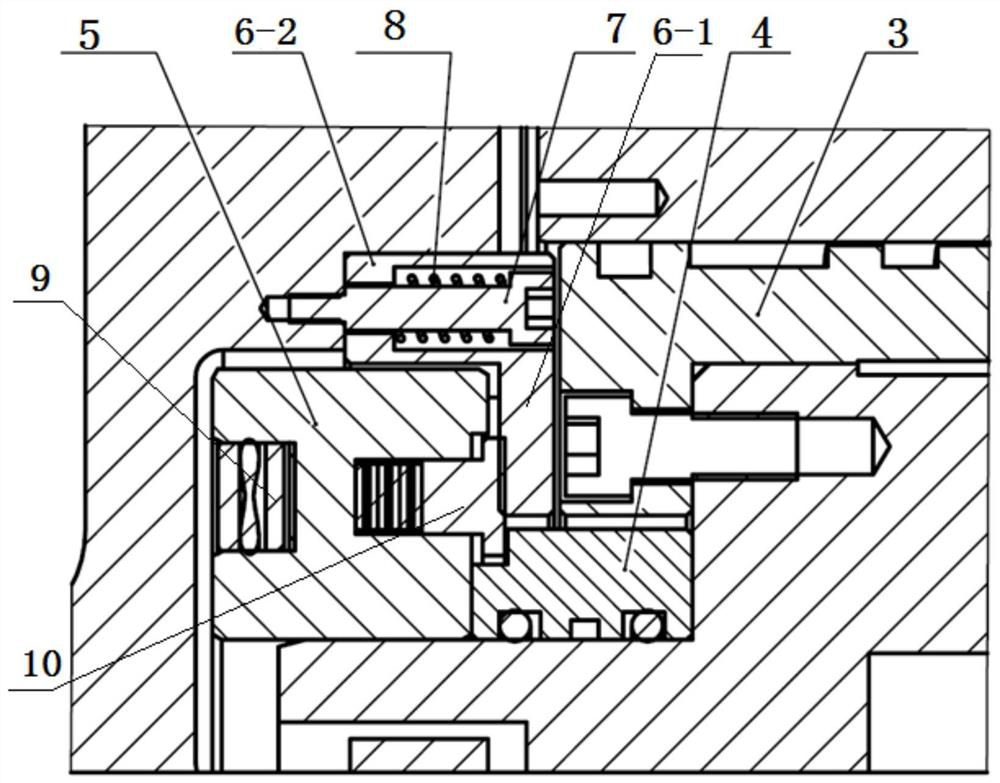
  • Figure 3
    Figure 3
Patent Text Reader

Abstract

The invention discloses a floating type numerical control rotary table safety locking structure. The floating type numerical control rotary table safety locking structure comprises a rotary table basebody and a rotary motion body, wherein a brake sleeve, an annular sleeve and a fixed seat are fixed to the rotary table base body in a sleeving manner; a locking ring which is in synchronous rotationalong with the rotary motion body is connected to the inner part of the rotary motion body; connecting bolts which are used for connecting the locking ring and the rotoary motion body are uniformly distributed on the locking ring; the locking ring can move in the axial direction of the connecting bolts; a reset spring which is used for applying force onto the locking ring to enable the locking ring to be propped against the rotary motion body is arranged on each connecting bolt in a sleeving manner; releasing oil cylinders are uniformly distributed on the fixed seat; a brake boot is fixed toa piston rod of each releasing oil cylinder; the releasing oil cylinders are monoactuated hydraulic cylinders; the compression springs are arranged in the front of the brake boots and the fixed seat,and can apply force to the brake boots in the direction facing the locking ring; and the brake boots can push the locking rings to move towards one side of the brake sleeve and is used for compactingthe locking ring on the brake sleeve.
Need to check novelty before this filing date? Find Prior Art

Description

technical field

[0001] The invention belongs to the field of metal cutting numerical control machine tools, and in particular relates to a safety locking structure of a floating numerical control turntable. Background technique

[0002] The CNC rotary table is the core functional component of the five-axis machining center, and its functional integrity and safety are the necessary requirements for the table.

[0003] The center of gravity of the swing axis of the two-axis CNC rotary table deviates from the center of rotation. From the perspective of safety and operation, the turntable is required to maintain the position before power failure in the event of power failure or emergency stop. At present, the CNC turntable uses spring force to compress the brake pads to deform and press the fixed surface for braking. There are a series of problems such as the difficulty in manufacturing thin brake pads, the permanent deformation of the brake pads and the abnormal friction noise,...

Examples

Embodiment Construction

[0016] Such as figure 1 with figure 2 The safety locking structure of the CNC turntable shown includes a turntable base body 1 and a rotary motion body 2 , the turntable base body 1 is fixed on the machine tool, and the rotary motion body 2 can rotate relative to the turntable base body 1 .

[0017] Such as figure 2 with image 3 As shown, a brake sleeve 3, an annular sleeve 4, and a fixed seat 5 are set on the turntable base 1, and the brake sleeve 3, annular sleeve 4, and fixed seat 5 are all fixed relative to the turntable base 1, as shown in the figure In the embodiment, the brake sleeve 3 is fixedly connected to the turntable base 1 by bolts, the annular sleeve 4 is fixedly connected to the turntable base 1 by bolts, and the fixing seat 5 is fixedly connected to the annular sleeve 4 by bolts.

[0018] Such as image 3 As shown, a locking ring 6 is connected to the rotary motion body 2, and the locking ring 6 can rotate synchronously with the rotary motion body 2. Co...