A high-precision arch dam deformation monitoring equipment and measurement method

A measurement method and deformation monitoring technology, applied in measurement devices, instruments, optical devices, etc., can solve the problems of angle intermediate variable error, can not fundamentally remove the disturbance of optical components, etc., to ensure accuracy, solve end point drift and beam Tilt problem, the effect of improving numerical precision

Active Publication Date: 2019-05-21
XI AN JIAOTONG UNIV +1
View PDF6 Cites 0 Cited by
  • Summary
  • Abstract
  • Description
  • Claims
  • Application Information

AI Technical Summary

Problems solved by technology

[0003] 1) Lasers and optical equipment will deform after working for a certain period of time, causing the light beam emitted by the light source to move and rotate in space. Existing solutions such as Lu Xinchun et al. in 2006 "Laser Beam Monitoring Accuracy of Dam Deformation Influencing factors and solutions" mentioned in the article, this method starts from the light source, obviously cannot fundamentally remove the disturbance caused by the spatial rotation of other optical components (such as optical refraction system)
[0004] 2) There are many calculation processes for the existing laser arch dam alignment system, such as the layout and calculation mentioned in the article "Application of Vacuum Laser Deformation Monitoring System in Xiaowan Hyperbolic Arch Dam" published by Peng Xinxin and others in 2015 Although this method is displacement deformation, it involves more angle intermediate variables in the calculation process, and the calculation of angle intermediate variables will introduce more errors

Method used


Image

  • A high-precision arch dam deformation monitoring equipment and measurement method
  • A high-precision arch dam deformation monitoring equipment and measurement method
  • A high-precision arch dam deformation monitoring equipment and measurement method

Examples


Embodiment Construction

[0056] The present invention will be further described in detail below in conjunction with specific embodiments, which are explanations of the present invention rather than limitations.

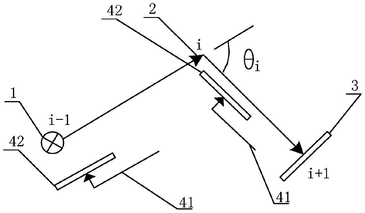
[0057] The present invention changes the original laser collimation principle to utilize Fresnel diffraction and a double reflector system, and adopts an arrangement method of angle measurement and distance measurement with repeatability to monitor deformation.

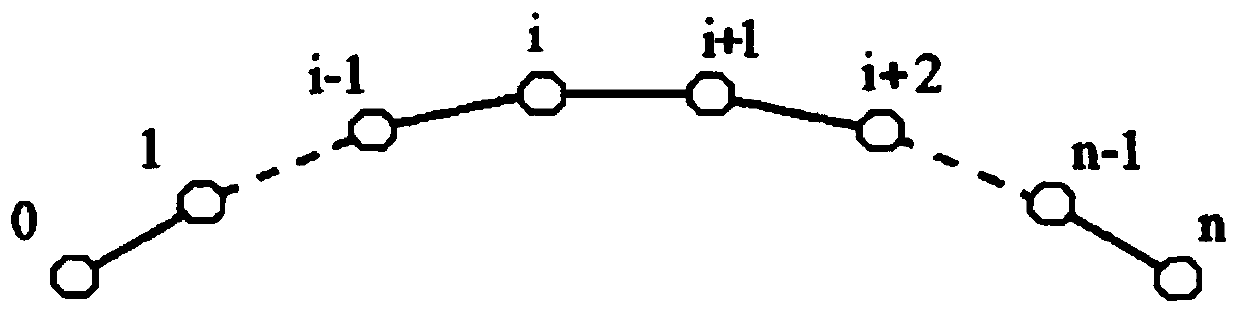
[0058] First, divide the arched dam into n measuring sections, n=0, 1, 2, ...i-1, i, i+1, ...n, where i is a natural number, and the two ends of the measuring section are measuring points , the first and last measuring points among several measuring points are respectively located at both ends of the dam body; each adjacent three measuring points is a measuring unit, and among the three measuring points of each measuring unit, respectively Set up different devices. The first measuring point places the emitting device 1, which is a p...


PUM


Abstract

A piece of high-precision dam deformation monitoring equipment and a measuring method belong to the field of measuring and monitoring. The equipment comprises a plurality of monitoring units. Each monitoring unit comprises an indium steel pipe system, and a transmitting device, a refracting device and a receiving device which cooperate with one another and are arranged along an optical path. Each indium steel pipe system comprises two indium steel pipes and length measurement position-sensitive sensors in one-to-one correspondence with the indium steel pipes, wherein the indium steel pipes are fixed at one measuring point of a measuring section, and the corresponding length measurement position-sensitive sensors are fixed at the other measuring point of the measuring section, and the corresponding indium steel pipes are connected through a moving pair with the measuring point at which the corresponding length measurement position-sensitive sensors are fixed. Through a plurality of monitoring units arranged in a triangular shape, dam deformation data is monitored and acquired from all measuring sections. The indium steel pipes of each indium steel pipe system are fixed at one measuring point, and the other measuring point is connected with the indium steel pipes through a moving pair. The noncontact mode of measurement and the stress-free mode of connection can eliminate deformation disturbance of the indium steel pipes caused by stress and ensure the accuracy of measurement.

Description

technical field [0001] The invention belongs to the field of measurement and monitoring, and relates to a deformation monitoring of an arch dam, in particular to a high-precision arch dam deformation monitoring device and a measurement method. Background technique [0002] The deformation monitoring of arch dams includes horizontal displacement monitoring, vertical displacement monitoring, horizontal and vertical simultaneous monitoring, and three-dimensional displacement monitoring. Among them, the closed laser collimation deformation monitoring technology using the principle of laser collimation is more advanced, but the existing laser arch dam deformation monitoring technology also has many shortcomings, the main shortcomings are as follows. [0003] 1) Lasers and optical equipment will deform after working for a certain period of time, causing the light beam emitted by the light source to move and rotate in space. Existing solutions such as Lu Xinchun et al. in 2006 "Las...

Claims


Application Information

Patent Timeline
Patent Type & Authority Patents(China)
IPC IPC(8): G01B11/16
CPCG01B11/16
Inventor 乐开端袁一涵李杰肖盾漆福栋黄启明
Owner XI AN JIAOTONG UNIV
Why Eureka
Try Eureka