
Cable pay-off device for communication engineering

A technology of communication engineering and pay-off device, applied in the field of communication, can solve problems such as narrow application scope, and achieve the effect of wide application scope

Inactive Publication Date: 2020-09-25
赵建红
View PDF1 Cites 1 Cited by
  • Summary
  • Abstract
  • Description
  • Claims
  • Application Information

AI Technical Summary

Problems solved by technology

[0003] But above-mentioned technical scheme also has following deficiency in actual use: bobbin is installed on the rotating shaft, drives bobbin to rotate by rotating shaft, can only be applicable to the bobbin of specific size, for the inner diameter of some bobbin central holes It is not suitable for different situations, and the scope of application is narrow

Method used


Image

  • Cable pay-off device for communication engineering
  • Cable pay-off device for communication engineering
  • Cable pay-off device for communication engineering

Examples


Embodiment 1

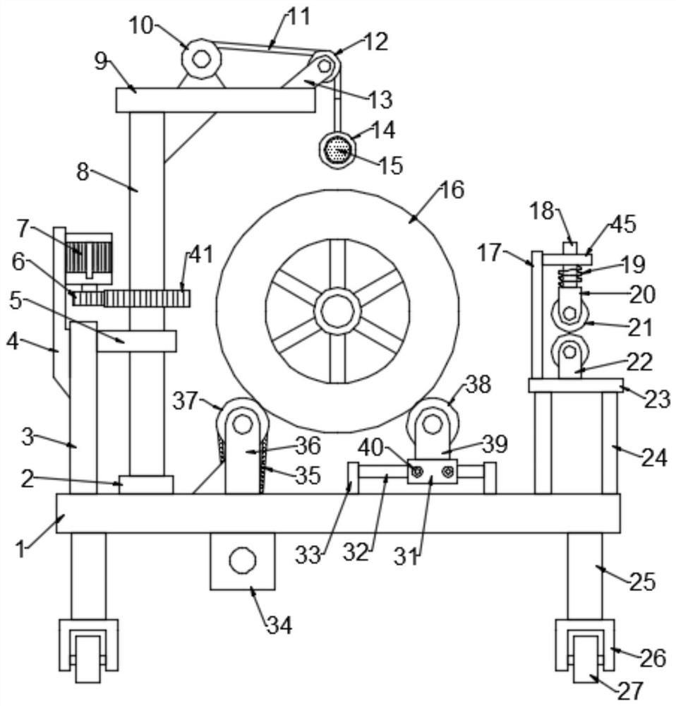
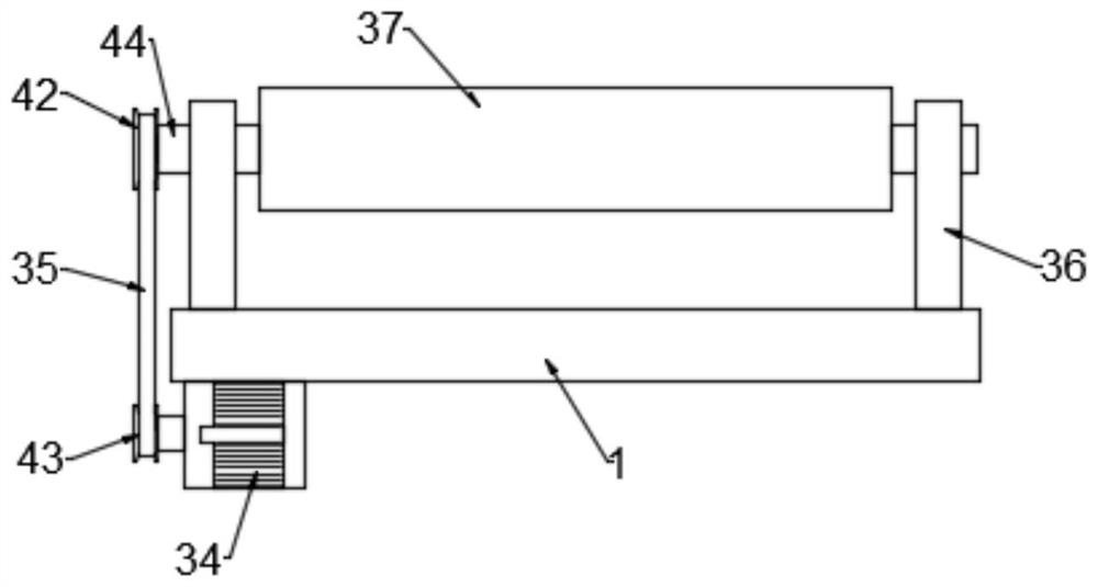
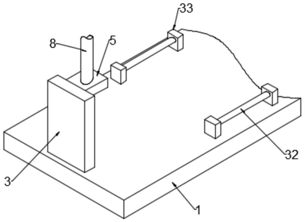
[0030] see Figure 1-3 , in an embodiment of the present invention, a cable pay-off device for communication engineering, comprising a load plate 1, the bottom of the load plate 1 is provided with legs 25, the bottom of the legs 25 is provided with a fourth wheel seat 26, the fourth wheel seat Rollers 27 are installed on the 26; the first roller base 36 is fixed on the bearing plate 1, the driving roller 37 is installed on the first roller base 36, and the driving assembly for driving the driving roller 37 is arranged on the bearing plate 1, carrying The upper side of the plate 1 is provided with a second roller seat 39, and the driven roller 38 is installed on the second roller seat 39, and an adjustment assembly for adjusting the position of the driven roller 38 is also provided on the carrier plate 1; The barrel 16 is placed on the driving roller 37 and the driven roller 38, the frame of the bobbin 16 is supported by the driving roller 37 and the driven roller 38, the drivi...

Embodiment 2

[0043] see Figure 4 , in an embodiment of the present invention, a cable pay-off device for communication engineering is different from Embodiment 1 in that a support plate 30 is fixed on the support leg 25, and a screw rod 29 is threaded on the support plate 30, and the screw rod 29 is The bottom end is provided with a pointed cone 28; by rotating the screw rod 29, the threaded cooperation between the screw rod 29 and the support plate 30 is used to make the pointed cone 28 descend, and the pointed cone 28 is inserted into the ground, so that the device can be fixed and the device can be prevented from moving during the setting-out process. .


PUM


Abstract

The invention relates to the technical field of communication, and provides a cable pay-off device for communication engineering. The cable pay-off device comprises a bearing plate, a first roller seat is fixed to the bearing plate, a driving roller is mounted on the first roller seat, a driving assembly for driving the driving roller to operate is arranged on the bearing plate, a second roller seat is arranged on the upper side of the bearing plate, a driven roller is mounted on the second roller seat, and an adjusting assembly for adjusting the position of the driven roller is further arranged on the bearing plate. According to the cable pay-off device for the communication engineering, the driving roller is driven to operate through a second motor, and the driving roller drives a winding reel to rotate so that a cable on the winding reel can be released; by moving a sliding block on a guide rod, the position of the driven roller can be adjusted, and the distance between the drivingroller and the driven roller is adjusted according to the specific size of the winding reel so as to be suitable for the winding reels of different sizes, and the application range is wide; and afterthe position is adjusted, a locking bolt is screwed to abut against the guide rod to fix the position of the sliding block.

Description

technical field [0001] The invention belongs to the technical field of communication, and in particular relates to a cable pay-off device for communication engineering. Background technique [0002] In the Chinese patent with the authorized announcement number CN206842750U, a communication cable pay-off device is disclosed, including a cart, a power supply, a pay-off device, a pole, a roller and a cutting device; There are rollers, a pay-off device in the middle of the top of the trolley, a cutting device on the right side of the pay-off device, a power supply on the left side of the top of the cart, and the power supply and the pay-off device are connected by wires. It can automatically rotate to release the cable, saving time and effort, and at the same time, it is convenient to cut the cable. [0003] But above-mentioned technical scheme also has following deficiency in actual use: bobbin is installed on the rotating shaft, drives bobbin to rotate by rotating shaft, can ...

Claims


Application Information

Patent Timeline
Patent Type & Authority Applications(China)
IPC IPC(8): B65H49/38B65H49/30B65H49/34B65H67/02B65H57/14
CPCB65H49/30B65H49/34B65H49/38B65H57/14B65H67/02B65H2701/34
Inventor 赵建红
Owner 赵建红
Learn More