Numerical control polycrystalline silicon diamond wire high-speed cutting-off machine

A diamond wire and cutting machine technology, which is applied to fine working devices, stone processing equipment, manufacturing tools, etc., can solve the problem that the loading, unloading and working areas are not independent, the freedom of worktable coordination is limited, and the worktable is not loaded. Convenience and other issues, to achieve the effect of shortening the truncation processing time, facilitating the feeding and cutting of the knife, and reducing the auxiliary processing time

Pending Publication Date: 2018-10-12
WUXI SHANGJI AUTOMATION
View PDF0 Cites 1 Cited by
  • Summary
  • Abstract
  • Description
  • Claims
  • Application Information

AI Technical Summary

Problems solved by technology

[0003] In the prior art, there are many shortcomings in the design and application of CNC diamond wire cutting equipment: for example, the cutting wire frame is fixed, the cutting wire wheel has limited positions, so that it has limited freedom of cooperation with the workbench, and the silicon that can be processed at one time The number of rods is limited; the tension and balance of the diamond wire mesh are easily controlled by the motor. The motor not only needs to rotate the winding reel to take in and out the wire, but also takes into account the tension and balance of the wire mesh, which is likely to cause wire breakage and poor equipment operation stability. Problem: It is inconvenient to load materials on the workbench, and the loading, unloading and working areas are not independent, resulting in labor-intensive operators, time-consuming and labor-intensive, and affecting production efficiency

Method used


Image

  • Numerical control polycrystalline silicon diamond wire high-speed cutting-off machine
  • Numerical control polycrystalline silicon diamond wire high-speed cutting-off machine
  • Numerical control polycrystalline silicon diamond wire high-speed cutting-off machine

Examples


Embodiment Construction

[0030] The specific implementation manner of the present invention will be described below in conjunction with the accompanying drawings.

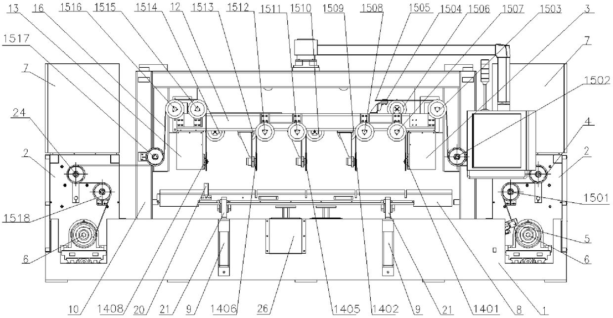
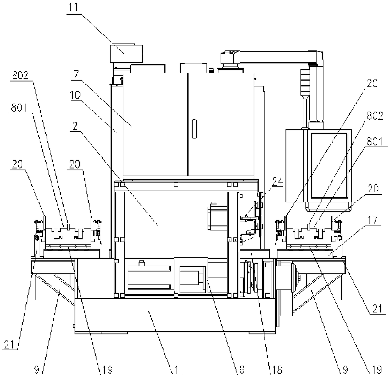
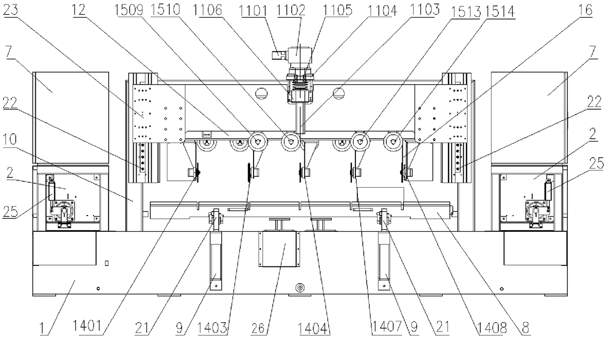
[0031] Such as figure 1 , figure 2 with image 3 As shown, the CNC polysilicon diamond wire high-speed cutting machine of this embodiment includes a bed 1, and the two ends of the bed 1 are respectively equipped with a take-up and release chamber 2, and an electric box 7 is fixedly installed on the upper part of the take-up and take-off chamber 2, and two retractable The four corners of the bed 1 between the wire chambers 2 are respectively fixed with upright columns 10, and two workbenches 8 are respectively installed between the two upright columns 10 on both sides of the bed 1 through the guide rail bracket 9, and the guide rail bracket 9 and the The worktables 8 are connected by short steel guide rails 17; the outer ends of the two columns 10 on the rear side are respectively installed with a sliding plate 23 through the linear guid...


PUM


Abstract

The invention relates to a numerical control polycrystalline silicon diamond wire high-speed cutting-off machine which comprises a lathe bed and taking-up and paying-off chambers installed at the twoends of the lathe bed. An electric box is fixedly installed on the upper portion of each taking-up and paying-off chamber. Stand columns are installed on the four corners of the lathe bed correspondingly. Two working tables are installed between the two stand columns located on the two sides of the lathe bed through guide rail supports correspondingly. The guide rail supports and the working tables are connected through short steel guide rails. Sliding plates are installed on the two stand columns located on the rear side through linear guide rails correspondingly. The sliding plates drive a cutting wire frame fixed to the lower portions of the sliding plates to move up and down. A first datum motor and a second datum motor are installed at the two ends of the cutting wire frame correspondingly. Multiple diamond wire passing wheels are installed on the two sides of the cutting wire frame. Multiple diamond wire cutting wheels are installed below the cutting wire frame. Diamond wires areguided out from the taking-up and paying-off chamber at one end and sequentially wound around the multiple diamond wire cutting wheels and the diamond wire passing wheels into the taking-up and paying-off chamber at the other end. According to the machine, the diamond wire taking-up, paying-off and distributing quality is improved, and the operation stability and the production efficiency of equipment are improved.

Description

technical field [0001] The invention relates to the technical field of polysilicon processing numerical control machine tool automation technology, in particular to a numerical control polysilicon diamond wire high-speed cutting machine. Background technique [0002] Due to the development of photovoltaic industry technology, users have put forward higher requirements for the production process and product quality of polysilicon, especially for the high efficiency, high speed, low energy consumption and low carbon production requirements of polysilicon diamond wire cutting equipment. [0003] In the prior art, there are many shortcomings in the design and application of CNC diamond wire cutting equipment: for example, the cutting wire frame is fixed, the cutting wire wheel has limited positions, so that it has limited freedom of cooperation with the workbench, and the silicon that can be processed at one time The number of rods is limited; the tension and balance of the diam...

Claims


Application Information

Patent Timeline
Patent Type & Authority Applications(China)
IPC IPC(8): B28D5/04
CPCB28D5/045B28D5/0058B28D5/0082
Inventor 杨阳杨昊杭菲董海杰管家辉
Owner WUXI SHANGJI AUTOMATION
Why Eureka
Try Eureka