
Quick installing device of hydraulic annular wellhead casing flange

A casing method and fast technology, applied in the direction of wellbore/well components, earthwork drilling, sealing/isolation, etc., can solve the problems of high risk, the inability of operators to install close to the wellhead, time-consuming and labor-intensive problems, and protect life safety , The clamping process is convenient and fast, and the effect of shortening the rescue time

Pending Publication Date: 2020-09-25
西安宇星石油机械新技术开发有限公司
View PDF0 Cites 0 Cited by
  • Summary
  • Abstract
  • Description
  • Claims
  • Application Information

AI Technical Summary

Problems solved by technology

[0004] The purpose of the present invention is to solve the problem existing in the prior art that when the well is killed by the well control device, the operator needs to install fastening bolts at close range to connect the casing flange and the lower flange of the wellhead cross, which is time-consuming and labor-intensive. In addition, when the pressure in the well is high or there is a fire, the operator cannot install it close to the wellhead, so a hydraulic annular wellhead casing flange quick installation device is provided

Method used


Image

  • Quick installing device of hydraulic annular wellhead casing flange
  • Quick installing device of hydraulic annular wellhead casing flange
  • Quick installing device of hydraulic annular wellhead casing flange

Examples


Embodiment Construction

[0054] In order to make the purpose, advantages and features of the present invention more clear, the hydraulic annular wellhead casing flange quick-installing device proposed by the present invention will be further described in detail below in conjunction with the accompanying drawings and specific embodiments.

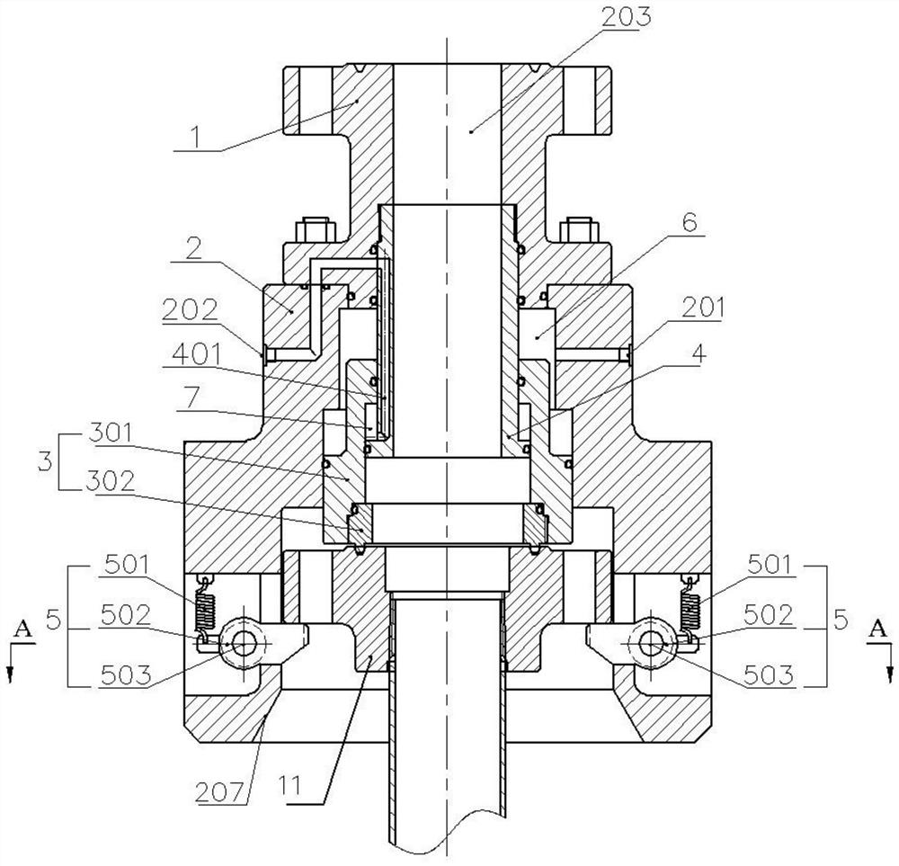
[0055] Such as figure 2 As shown, the device includes a main housing, an inner cylinder 4 , a piston assembly 3 , and at least two quick locking assemblies 5 .

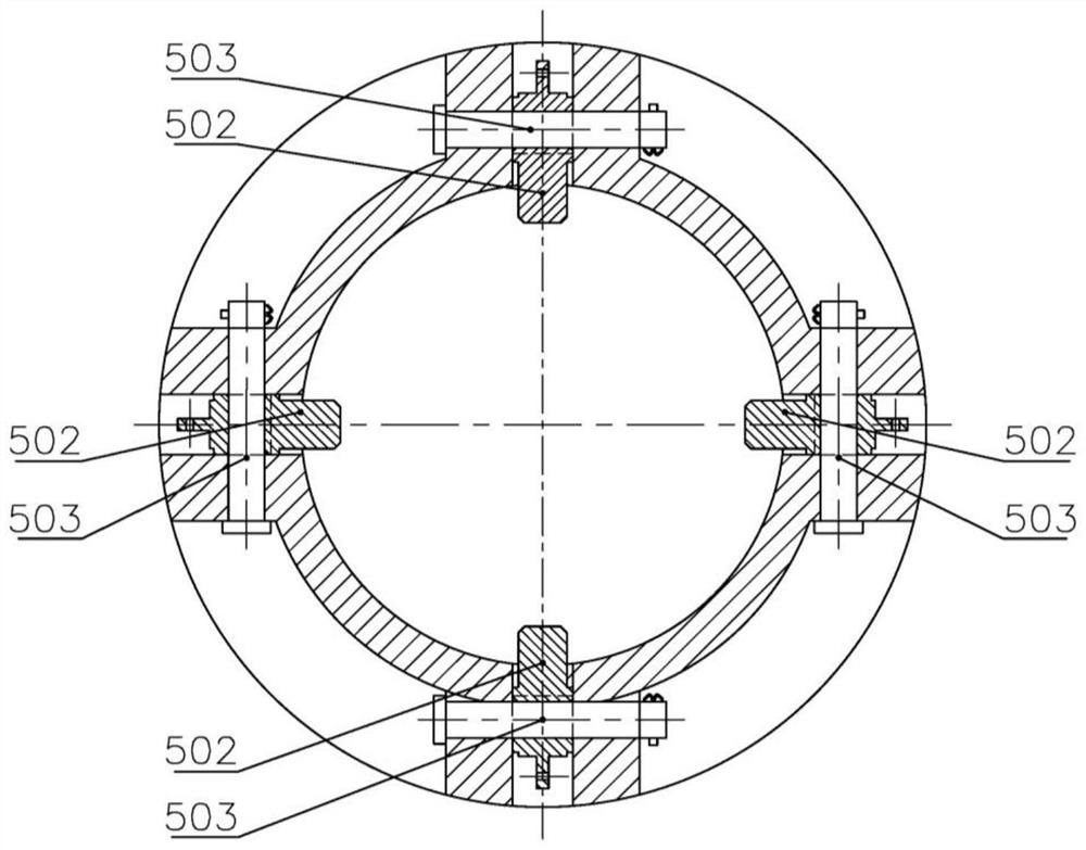
[0056] The main shell such as Figure 2 to Figure 5 As shown, it includes the body 2, the upper transition flange 1 arranged on the upper end of the body 2, and the inner cavity 203 that penetrates up and down. Cavity, in this embodiment, the upper opening cavity is located in the upper transition flange 1, and the piston cavity and sleeve flange accommodating cavity are located in the body 2. The inner cylinder 4 is coaxially arranged in the inner cavity 203, and its upper part is fixedly connected with...


PUM


Abstract

The invention relates to a quick installing device of a hydraulic annular wellhead casing flange. The quick installing device comprises a main shell, an inner cylinder barrel, a piston assembly and atleast two rapid locking assemblies, wherein the main shell comprises an inner cavity which is through up and down, and the inner cavity comprises an upper opening cavity, a piston cavity and a casingflange containing cavity which are distributed from top to bottom; the inner cylinder barrel is coaxially arranged in the inner cavity, the upper portion of the inner cylinder barrel is fixedly connected with the inner wall at the upper opening cavity corresponding to the main shell, and the lower portion is located in the piston cavity; the piston assembly is located in the piston cavity and sleeves the outer side of the inner cylinder barrel in a sliding manner; an upper sealing cavity is formed among the main shell, the inner cylinder barrel and the piston assembly, and a lower sealing cavity is formed between the piston assembly and the inner cylinder barrel; an upper sealing cavity oil inlet and outlet hole communicated with the upper sealing cavity is formed in the main shell, a transition oil inlet and outlet hole communicated with a lower sealing cavity is formed in the side wall of the inner cylinder barrel, and a lower sealing cavity oil inlet and outlet hole communicated with the transition oil inlet and outlet hole is formed in the main shell; and the casing flange can be clamped in the casing flange accommodating cavity by a quick locking assembly.

Description

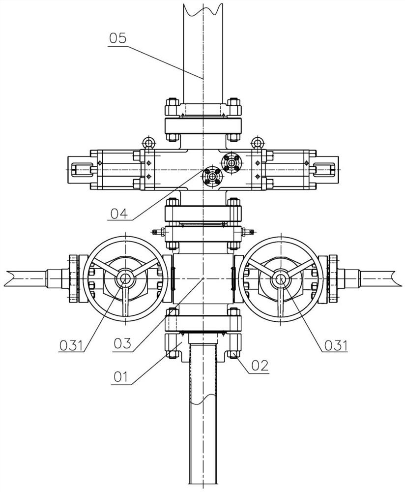
technical field [0001] The invention relates to well control equipment used in oil fields, in particular to a hydraulic annular wellhead casing flange quick installation device. Background technique [0002] At the oil field operation site, there will be a special situation for the production casing of oil, water and gas wells on the ground, that is, blowout, well kick or fire accidents will occur when the upper end of the wellhead casing flange is not connected to any well control equipment . [0003] The prior art solves the above problems generally by installing a well control device on the upper end of the casing flange. The well control device is such as figure 1 As shown, it includes the wellhead cross 03, the hydraulic (or manual) gate valve 031 on both sides of the wellhead cross 03, the hydraulic ram blowout preventer 04 connected to the upper end of the wellhead cross 03, and the hydraulic ram blowout preventer The fire starter 05 connected to the upper end of 04...

Claims


Application Information

Patent Timeline
Patent Type & Authority Applications(China)
IPC IPC(8): E21B33/03E21B33/06
CPCE21B33/03E21B33/06
Inventor 孙国玉唐永生郭琰娄真真聂斌姜同飞王静刘达为孙剑峰雷宽成
Owner 西安宇星石油机械新技术开发有限公司
Learn More