System and method for measuring resonant frequency of MEMS piezoelectric actuators

A piezoelectric actuator and resonant frequency technology, applied in the field of MEMS, can solve the problems of unsuitability for MEMS piezoelectric actuator measurement experiments, complicated operation steps, high equipment requirements, etc., meet the requirements of fast and accurate measurement, low cost, and high measurement efficiency Effect

Inactive Publication Date: 2020-09-25
SHANGHAI INST OF TECH
View PDF7 Cites 1 Cited by
  • Summary
  • Abstract
  • Description
  • Claims
  • Application Information

AI Technical Summary

Problems solved by technology

However, this patented technology has high requirements for equipment, high experimental cost, and complicated operation steps, which is not suitable for the measurement experiment of MEMS piezoelectric actuators in practical applications.

Method used


Image

  • System and method for measuring resonant frequency of MEMS piezoelectric actuators
  • System and method for measuring resonant frequency of MEMS piezoelectric actuators
  • System and method for measuring resonant frequency of MEMS piezoelectric actuators

Examples


Embodiment 1

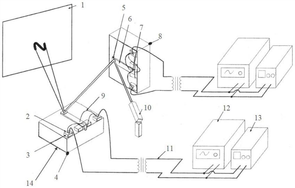
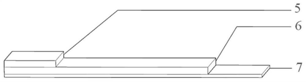
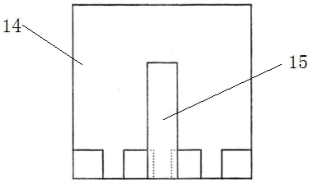
[0036] A system for measuring the resonant frequency of a MEMS piezoelectric actuator, comprising a piezoelectric actuator 15, a base 14 for installing the piezoelectric actuator, a driving power supply device for driving the piezoelectric actuator 15, a laser pointer 10 and A fluorescent screen 1 for displaying laser light; a piezoelectric actuator 15 and its corresponding base form an execution platform. Such as Figure 6 As shown, when working, the driving power supply device applies a voltage with a certain frequency change on the piezoelectric ceramic sheet 6, and the laser light generated by the laser pointer 10 is reflected by the reflector of the piezoelectric actuator 15 in turn to display a straight line on the fluorescent screen 1, such as figure 2 and image 3 As shown, the piezoelectric actuator 15 is a cantilever beam structure, including a copper sheet 7 whose end is fixed on the base 14, a piezoelectric ceramic sheet 6 to be measured bonded to the suspended p...

Embodiment 2

[0045] A system for determining the resonant frequency of MEMS piezoelectric actuators, such as figure 1 As shown, it includes two piezoelectric actuators 15, a base 14 for installing the piezoelectric actuators, a driving power supply device for driving the piezoelectric actuators 15, a laser pointer 10, and a fluorescent screen 1 for displaying laser light; The piezoelectric actuator 15 and its corresponding base form an execution platform, such as figure 1 x executes platform 4 and y executes platform 8. When working, the driving power supply device applies a voltage with a certain frequency change on the piezoelectric ceramic sheet 6, and the laser light generated by the laser pointer 10 is reflected by the reflectors of the two piezoelectric actuators 15 in turn and then displayed on the fluorescent screen 1. Two-dimensional Lissajous graphics, such as figure 2 and image 3 As shown, the piezoelectric actuator 15 is a cantilever beam structure, including a copper shee...


PUM

PropertyMeasurementUnit
thicknessaaaaaaaaaa

Abstract

The invention relates to a system for measuring the resonant frequency of MEMS piezoelectric actuators. The system comprises one or more piezoelectric actuators, a base used for installing the piezoelectric actuators, a driving power supply device used for driving the piezoelectric actuators, a laser pointer and a fluorescent screen used for displaying laser. The piezoelectric actuatorsare of a cantilever beam structure and each comprises a copper sheet with the end fixed to the base, a piezoelectric ceramic piece to be tested bonded to the suspension portion of the copper sheet, and a reflector bonded to the piezoelectric ceramic piece and located at the free end of the cantilever beam structure. The laser generated by the laser pointer is reflected by reflecting mirrors of the piezoelectric actuators in sequence and then a graph is displayed on the fluorescent screen; and the driving power supply device applies voltages with different frequencies to the piezoelectric ceramic piece. Compared with the prior art, the performance of the MEMS piezoelectric actuator in actual use can be rapidly and accurately evaluated, and the system has the advantages of being high in operability, low in cost, easy, convenient and rapid to install and measure and the like.

Description

technical field [0001] The invention relates to the field of MEMS, in particular to a system and method for measuring the resonant frequency of a MEMS piezoelectric actuator. Background technique [0002] The piezoelectric effect includes direct piezoelectric effect and inverse piezoelectric effect. The positive piezoelectric effect refers to the deformation of the piezoelectric material under external excitation, which causes the change of the internal stress of the material, and the displacement of the internal charge generates an electric field; the external electric field changes the position of the internal charge of the piezoelectric crystal, causing the piezoelectric crystal to Deformation occurs in a certain direction, which is the inverse piezoelectric effect. [0003] The experiment and measurement of the resonant frequency of traditional piezoelectric materials usually adopt the positive piezoelectric effect, that is, the vibration is generated by applying extern...

Claims


Application Information

Patent Timeline
Patent Type & Authority Applications(China)
IPC IPC(8): G01H11/08G01R31/00
CPCG01H11/08G01R31/00
Inventor 李以贵王保志张成功董璇
Owner SHANGHAI INST OF TECH
Why Eureka
Try Eureka