3D display module

A display module and module technology, applied in the field of 3D display, can solve the problems of reducing the service life of the lamp group, large brightness loss, and increasing the average current of the lamp group, etc.

Active Publication Date: 2020-09-25
NINGBO VISION DISPLAY TECH
View PDF18 Cites 0 Cited by
  • Summary
  • Abstract
  • Description
  • Claims
  • Application Information

AI Technical Summary

Problems solved by technology

However, the polarized 3D display technology has a certain loss in the brightness of the display screen, and the brightness loss is about 40%. Usually, the brightness adjustment method of the display screen is realized by software, which is also a common practice in the industry. Change the PWM duty cycle of the display driver to achieve brightness changes; the other is to load different enab

Method used


Image

  • 3D display module
  • 3D display module
  • 3D display module

Examples


Embodiment Construction

[0029] The technical solutions in the embodiments of the present application will be described below with reference to the drawings in the embodiments of the present application.

[0030] It should be noted that like numerals and letters denote similar items in the following figures, therefore, once an item is defined in one figure, it does not require further definition and explanation in subsequent figures. Meanwhile, in the description of the present application, the terms "first", "second" and the like are only used to distinguish descriptions, and cannot be understood as indicating or implying relative importance.

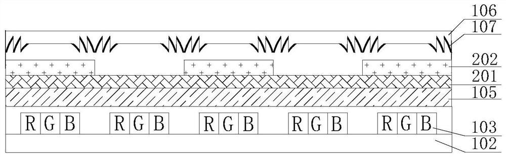
[0031] Please refer to figure 1 , figure 1 The schematic structural diagram of the first 3D display module provided in the embodiment of this application, the following will figure 1 The modules shown are elaborated, and the modules include:

[0032] Substrate 102;

[0033] Lamp groups 103 are arranged at intervals on the first surface of the substrate 102...


PUM

PropertyMeasurementUnit
Lengthaaaaaaaaaa

Abstract

The application provides a 3D display module. The 3D display module comprises a substrate, lamp sets arranged on a first surface of the substrate at intervals, a linear polarization film layer horizontally arranged on a second surface of the lamp sets, a phase difference compensation film layer horizontally arranged on a third surface, opposite to the second surface, of the linear polarization film layer, and a specially-shaped microstructure layer horizontally arranged on a fourth surface of the 1/2 phase difference compensation film layer; the fourth surface and the third surface are oppositely arranged; sawtooth-shaped groove structures are arranged on the fifth surface of the specially-shaped microstructure layer at intervals, and reflecting materials are arranged on the surfaces of the sawtooth-shaped groove structures and used for reflecting scattered light of the lamp sets back to the lamp sets; the first gap between every two adjacent sawtooth-shaped groove structures corresponds to one lamp set. Therefore, the light source utilization rate of the lamp sets is increased through the module, and a problem of lamplight invasion of the lamp sets is solved.

Description

technical field [0001] The present application relates to the technical field of 3D display, in particular, to a 3D display module. Background technique [0002] Polarized 3D display technology uses the principle that light has a "polarization direction" to decompose the original image. By adding a polarizing plate to the display screen, two pictures with different polarization directions can be sent to the viewer. When the picture passes through polarized glasses, due to the polarization Each lens of the type glasses can only accept pictures in one polarization direction, so that the left and right eyes of a person can receive two sets of pictures, and then form stereoscopic vision through brain fusion. [0003] Polarized 3D display technology effectively avoids the problems of active shutter technology such as the need to charge glasses, high maintenance costs, strong flickering feeling, and damage to eyesight. It is currently the mainstream technology in large-scale 3D us...

Claims


Application Information

Patent Timeline
IPC IPC(8): G02B30/25G02B5/30
CPCG02B30/25G02B5/3083
Inventor 王华波倪婷婷顾开宇魏厚伟杨枫张文龙董家亮贺炫辰
Owner NINGBO VISION DISPLAY TECH
Why Eureka
Try Eureka