

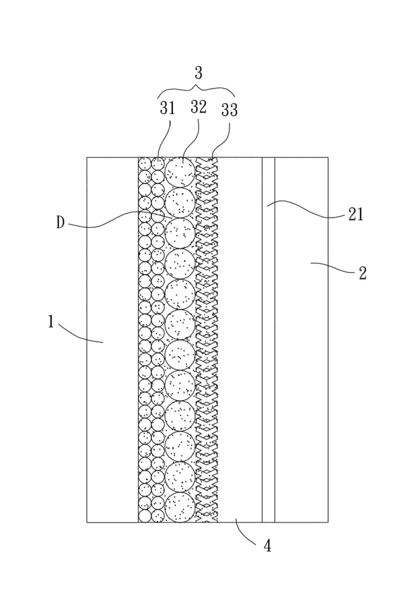
Dye-sensitized solar cell, its photoelectrode and producing method thereof
a solar cell and dye-sensitive technology, applied in the field of dye-sensitive solar cells, can solve the problems of limited light absorption and scattering, inability to increase the electron transfer rate of the photoanode, and inability to provide significant improvement in the photoelectric conversion efficiency of the photoanode, so as to achieve the effect of improving the photoelectric conversion efficiency
- Summary
- Abstract
- Description
- Claims
- Application Information
AI Technical Summary
Benefits of technology
Problems solved by technology
Method used
Image

Examples
example 1
NP20 / NS / NT
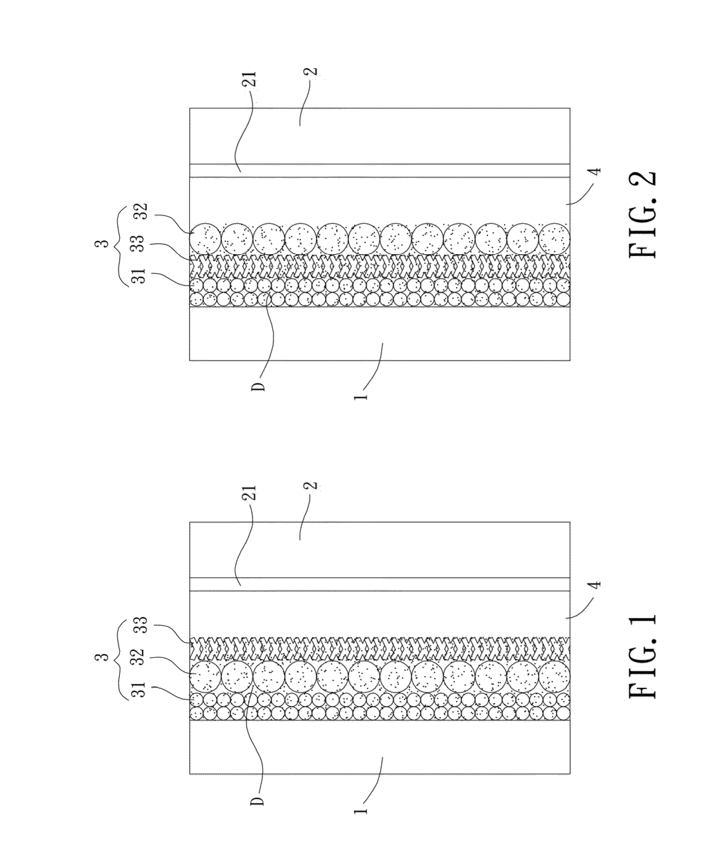
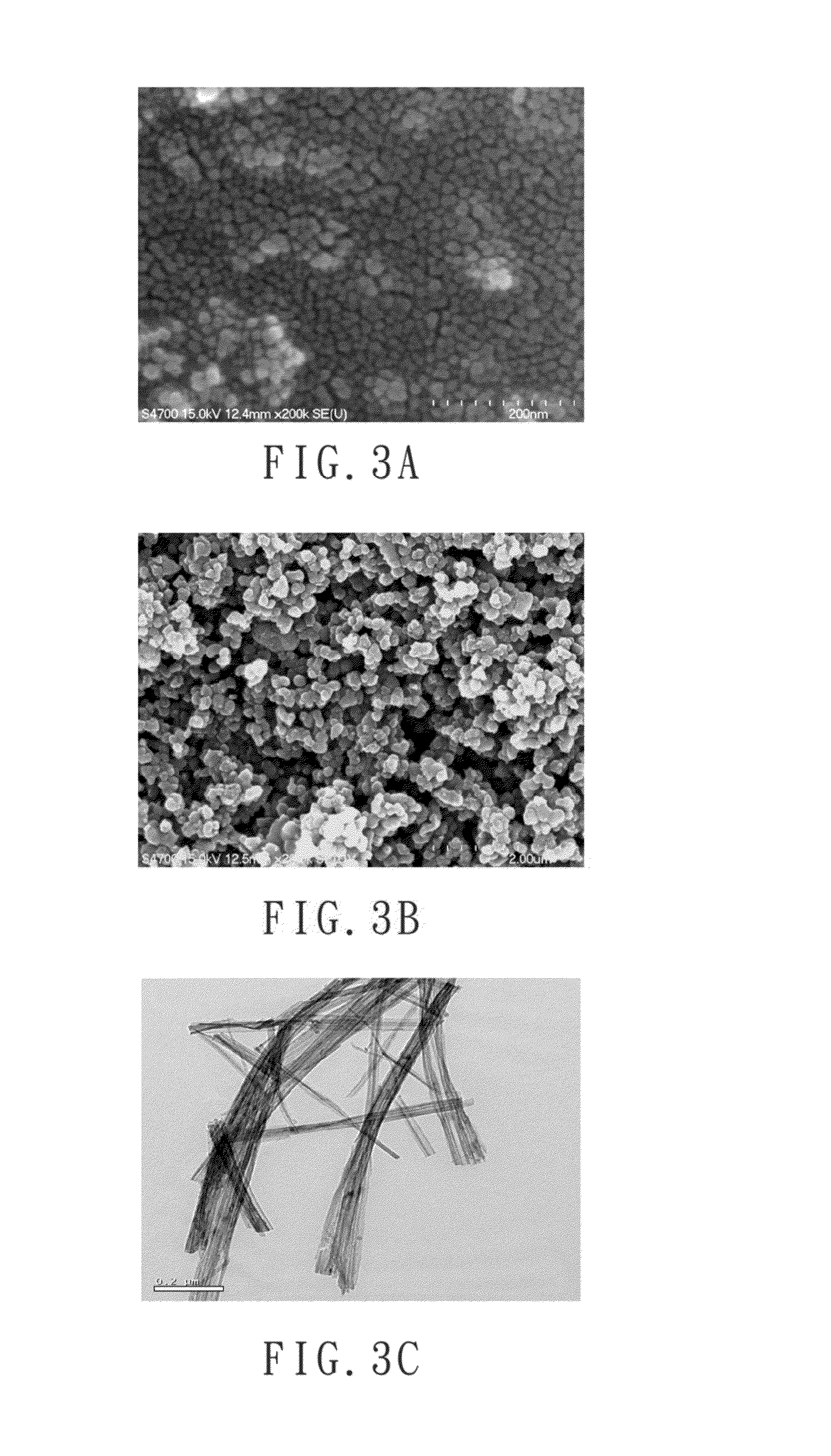
[0049]The particle-shaped paste (NP20) was applied to a substrate coated with fluorine-doped tin oxide and dried at 80° C. for 30 minutes. The substrate was then placed in a calciner and heated to 450° C. and remained at this temperature for 30 minutes, with the temperature increasing rate of the calciner controlled to be 10° C. / min. After cooling to the room temperature, a layer of NP20 (the dense layer 31, FIG. 4A shows its surface pattern) having a thickness of about 4.8 μm was formed on a surface of the substrate. The sphere-shaped plating liquid (NS) was coated on the layer of NP20 and dried at the room temperature. Then, multi-stage calcination was carried out, with the temperature increasing rate of the calciner controlled to be 5° C. / min. The calciner remained at 100° C. for 15 minutes, remained at 150° C. for 15 minutes, and remained at 450° C. for 30 minutes. After cooling to the room temperature, a layer of NP (the scattering layer 32, FIG. 4B shows its surface ...
example 2
NP20 / NT / NS
[0050]The production procedures of example 1 were carried out, with the stacking relation changed to produce a photoelectrode formed by NP20 / NT / NS on the substrate. Detailed description is not set forth to avoid redundancy
example 3
NT / NP20 / NS
[0051]The production procedures of example 1 were carried out, with the stacking relation changed to produce a photoelectrode formed by NT / NP20 / NS on the substrate. Detailed description is not set forth to avoid redundancy.
[0052]In addition to the above three examples of NP20 / NS / NT, NP20 / NT / NS, and NT / NP20 / NS, two-layer photoelectrodes formed by NP20 / NS and NP20 / NT and a photoelectrode formed by a single layer of NP20 were made and served as comparative examples for comparison with examples 1, 2, and 3.
[0053]Detailed procedures of the hydrothermal process for producing different types of titanium dioxide can be varied by one skilled in the art to produce powders of titanium dioxide nanoparticles having a diameter of 15-20 nm, powders of titanium dioxide nanospheres having a diameter of 200-500 nm, and powders of titanium dioxide nanotubes having a length of 300-800 nm. An example of the hydrothermal process is set forth below without any limitative purposes.
[0054](NP20 Hav...
PUM
 Abstract
Description
Claims
Application Information