Side light type back light source module

A backlight and side-light technology, which is applied in the field of side-light backlight modules, can solve the problems of low effective utilization of light sources, poor brightness, and inability to be recycled.

Inactive Publication Date: 2008-04-09
BOE TECH GRP CO LTD
View PDF0 Cites 2 Cited by
  • Summary
  • Abstract
  • Description
  • Claims
  • Application Information

AI Technical Summary

Problems solved by technology

However, part of the light is still directly emitted from other sides of the light guide plate 13, and most of this part of light is absorbed by the frame 16 and cannot be recycled.
[0004] Therefore, the effective utilization rate of the light source of the existing backlight module is low, and the brightness is poor.

Method used


Image

  • Side light type back light source module
  • Side light type back light source module
  • Side light type back light source module

Examples


Embodiment Construction

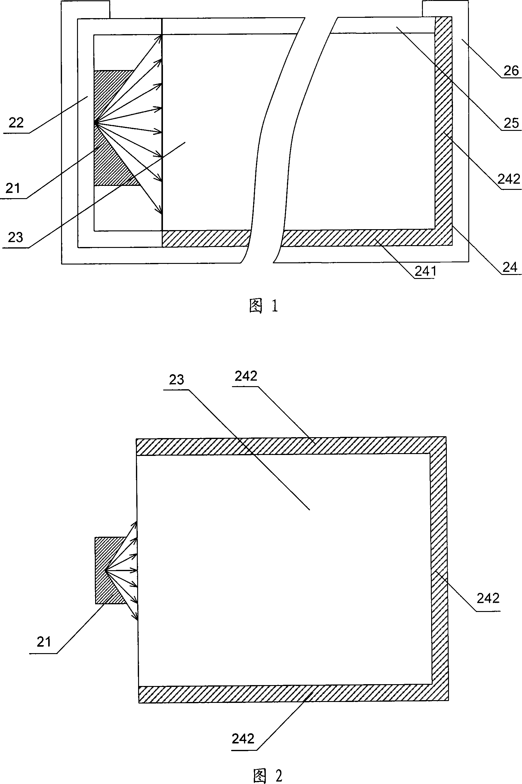
[0025] Fig. 1 is a schematic cross-sectional view of Embodiment 1 of the side-lit backlight module of the present invention. As shown in Fig. 1, the present invention includes a light source 21 for generating light; a light guide plate 23 for reflecting the light generated by the light source 21 and Refraction; the optical module 25 is covered on one side of the light guide plate 23, and is used to receive light from the light guide plate 23 to generate a surface light source; the reflection plate 24 including the bottom reflection plate 241 and the side reflection plate 242 is covered on the said light guide plate 23. The remaining sides of the light guide plate 23 are used to reflect light back into the light guide plate 23 ; the frame 26 is covered outside the reflective plate 24 .

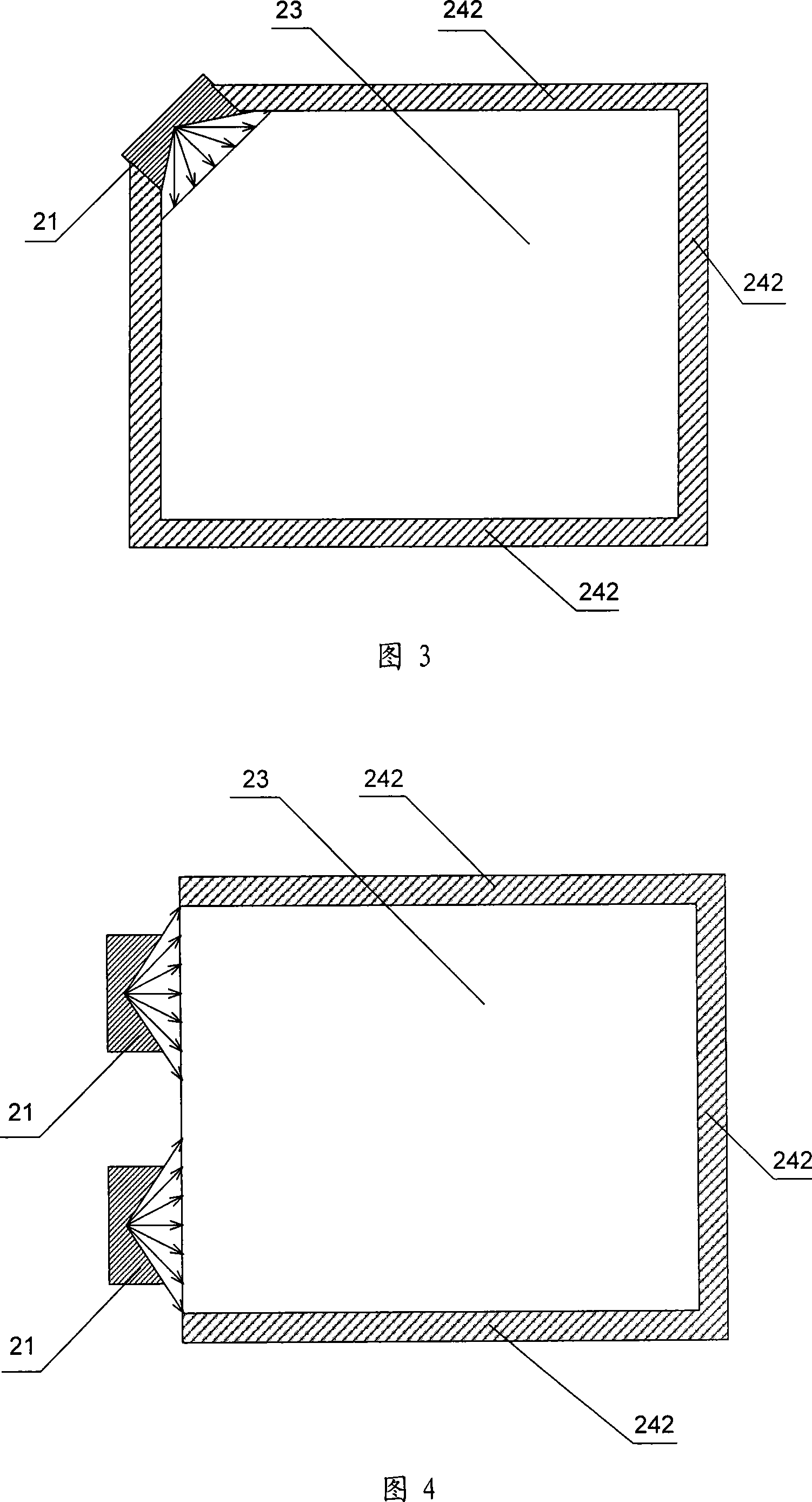
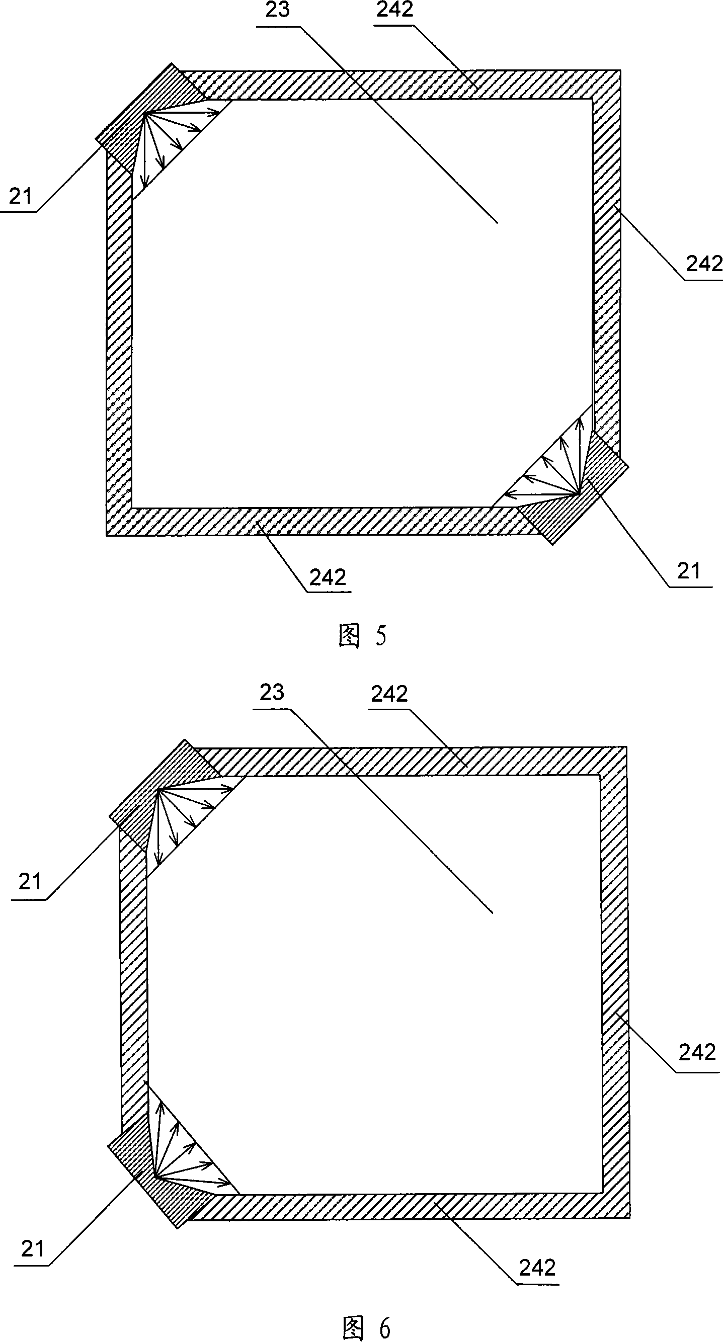
[0026] Specifically, as shown in FIG. 2 , it is a layout diagram of a point light source and a side reflector in this embodiment. The light source 21 is located on one side of the side of the li...


PUM


Abstract

The invention relates to a side light backlight module, which comprises a light source used for producing light beam; a light conductive board used for reflecting and refracting the light beam produced by the light source; an optical module covered on one side of the light conductive board used for receiving the light beam of the light conductive board and producing a plane light source; a reflective board comprises a bottom reflective board and a side reflective board and covered on the other sides of the light conductive board and is used for reflecting back the light beam to the light conductive board; a frame covered on the outer side of the light conductive board. The side reflective board of the side light backlight module can reflect back the light leaked from the light conductive board, the light is reflected by the bottom reflective board and again sent to the light output surface of the light conductive board so as to circularly use, the conversion efficiency between the point or line and plane light source of the backlight module is improved, the using efficiency of the backlight module is enhanced, and the backlight brightness is also improved.

Description

technical field [0001] The invention relates to a backlight module, in particular to a side-light backlight module of a light source reflection plate. Background technique [0002] With the development of display technology, the display will become thinner and thinner, and the brightness will be higher and higher, and the application of liquid crystal display technology will also increase. The application in products such as liquid crystal displays has also realized the thinning and thinning of display modules. However, it is still difficult to realize high brightness of liquid crystal display at present, the main reason is that the utilization rate of the backlight in the liquid crystal display module is very low. [0003] The edge-lit backlight module converts point light sources or line light sources into surface light sources. Improving the conversion efficiency between light sources can increase the brightness of the backlight, thereby increasing the brightness of the ...

Claims


Application Information

Patent Timeline
IPC IPC(8): G02F1/13357F21V7/00G02F1/1335
Inventor 王庆江万丽芳刘敬伟赵星星王刚邵喜斌张振彪
Owner BOE TECH GRP CO LTD
Why Eureka
Try Eureka