Plug-in switch device with concave surface

A switchgear, pluggable technology, applied in protection switches, emergency protection devices, parts of protection switches, etc., can solve the problems of wear and tear of nameplates and signs, reduce complaints, improve economic benefits, and improve long-term reliability. sexual effect

Pending Publication Date: 2020-09-25
上海瑞忒尔电气技术有限公司 +1
View PDF0 Cites 3 Cited by
  • Summary
  • Abstract
  • Description
  • Claims
  • Application Information

AI Technical Summary

Problems solved by technology

[0004] The purpose of this invention is to improve the heat dissipation capacity of the circuit breaker product after it is spliced ​​and ass

Method used


Image

  • Plug-in switch device with concave surface
  • Plug-in switch device with concave surface
  • Plug-in switch device with concave surface

Examples


Embodiment 1

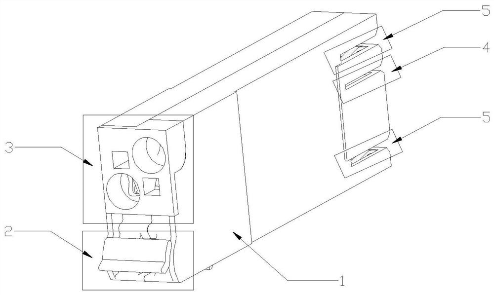
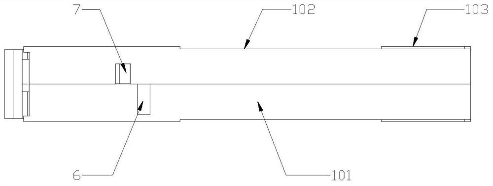
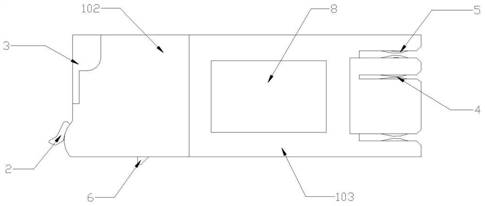
[0025] see Figure 1-4 , in an embodiment of the present invention, a pluggable switch device with a concave surface, including a housing 1, a housing body 101, a positioning surface 102, a groove 103, an operating end 2, an incoming and outgoing wire end 3, a signal port 4, an incoming and outgoing wire Clamping port 5, buckle 6, positioning groove 7, product nameplate 8, the overall shell (1) is a long rectangle, the side surface of the shell 1 is provided with a groove 103, and the front end surface of the shell 1 is provided with an operating end 2 and the cable inlet and outlet terminal 3, the signal port 4 and the cable inlet and outlet clamping port 5 are arranged on the rear end surface, and the buckle 6 and the positioning groove 7 are arranged on the bottom surface.

[0026] Wherein: the shell 1 includes a shell main body 101, and the left and right sides of the shell main body 101 are provided with a positioning surface 102 and a groove 103, and the positioning surf...

Embodiment 2

[0034] see Figure 5 , in an embodiment of the present invention, a pluggable switch device with a concave surface, including a housing 1, a housing body 101, a positioning surface 102, a groove 103, an operating end 2, an incoming and outgoing wire end 3, a signal port 4, an incoming and outgoing wire Clamping port 5, buckle 6, positioning groove 7, product nameplate 8, the overall shell (1) is a long rectangle, the side surface of the shell 1 is provided with a groove 103, and the front end surface of the shell 1 is provided with an operating end 2 and the cable inlet and outlet terminal 3, the signal port 4 and the cable inlet and outlet clamping port 5 are arranged on the rear end surface, and the buckle 6 and the positioning groove 7 are arranged on the bottom surface.

[0035] Wherein: the shell 1 includes a shell main body 101, and the left and right sides of the shell main body 101 are provided with a positioning surface 102 and a groove 103, and the positioning surfac...


PUM


Abstract

The invention provides a plug-in switch device with a concave surface. The plug-in switch device comprises a shell, wherein the whole shell is in a long-strip rectangular shape, a groove is formed inthe side surface of the shell, a product nameplate is arranged in the groove, an operation end and a wire inlet/outlet end are arranged on the front side end surface of the shell, a signal port and awire inlet/outlet clamping port are formed in the rear side end face, and a buckle and a positioning groove are formed in the bottom face. According to the invention, a positioning face and a groove structure are arranged on the two sides of a shell, wherein the air circulation amount can be increased through the arrangement of the groove, so that work of parts at the over-high temperature is reduced, and the long-term use reliability of a product is improved; and a mark surface and a nameplate surface placing surface are changed, and the product nameplate is arranged in the side groove structure so as to reduce abrasion to the nameplate structure in the installation process and prevent the influence on product appearance and product model information identification caused by nameplate abrasion, so that complaints of a client using end on a product due to the marking face and the nameplate are reduced, and the good development prospect is achieved.

Description

technical field [0001] The invention relates to the technical field of low-voltage electrical equipment, in particular to a plug-in switch device. Background technique [0002] Circuit breakers are divided into high-voltage circuit breakers and low-voltage circuit breakers according to their scope of use. Low-voltage circuit breaker, also known as automatic switch, commonly known as "air switch", also refers to low-voltage circuit breaker. It is an electrical appliance that not only has the function of manual switch, but also can automatically protect against voltage loss, undervoltage, overload, and short circuit. It can be used to distribute electric energy, start asynchronous motors infrequently, protect power lines and motors, etc., and can automatically cut off the circuit when they have severe overload, short circuit and undervoltage faults. Its function is equivalent to a fuse switch and The combination of overheating and underheating relays, etc., and generally does...

Claims


Application Information

Patent Timeline
IPC IPC(8): H01H71/02H01H71/06H01H71/08
CPCH01H71/0214H01H71/06H01H71/08
Inventor 王斌付志军周文静候志红
Owner 上海瑞忒尔电气技术有限公司
Why Eureka
Try Eureka