Electronic equipment and concealable charging connector thereof
A technology for charging connectors and electronic equipment, applied in the direction of connection, current collector, battery circuit device, etc., can solve the problems of scratching clothes or soft objects, the connector is easily damaged, and inconvenient to use, so as to avoid other damage or inconvenience. , Reduce the probability of damage and increase the effect of service life
- Summary
- Abstract
- Description
- Claims
- Application Information
AI Technical Summary
Problems solved by technology
Method used
Image

Examples
Embodiment Construction
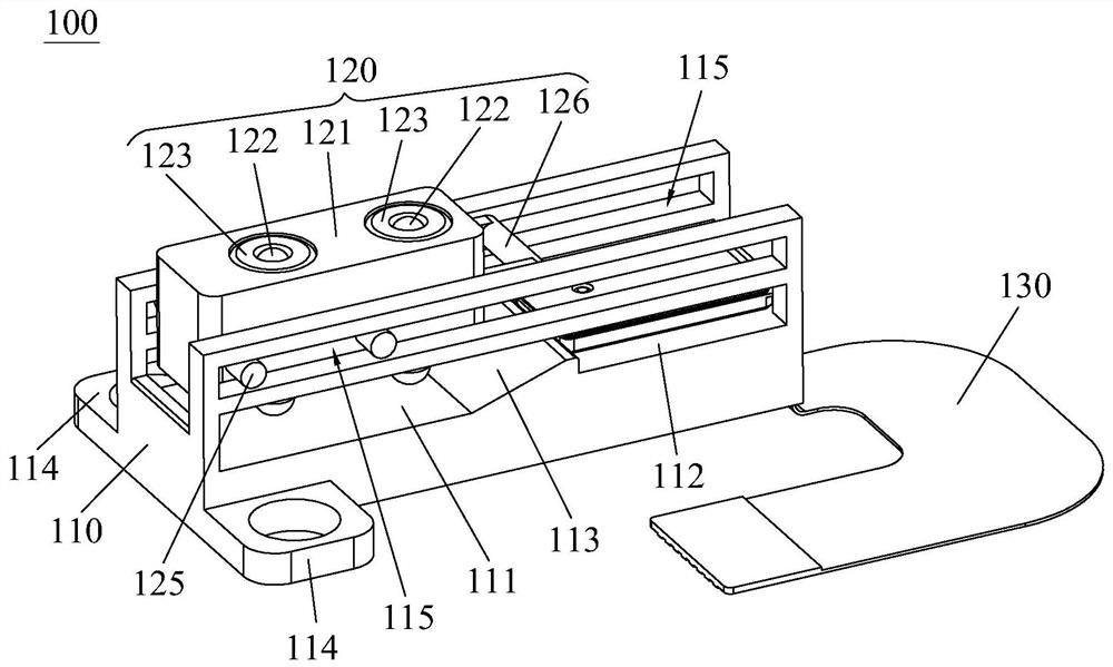
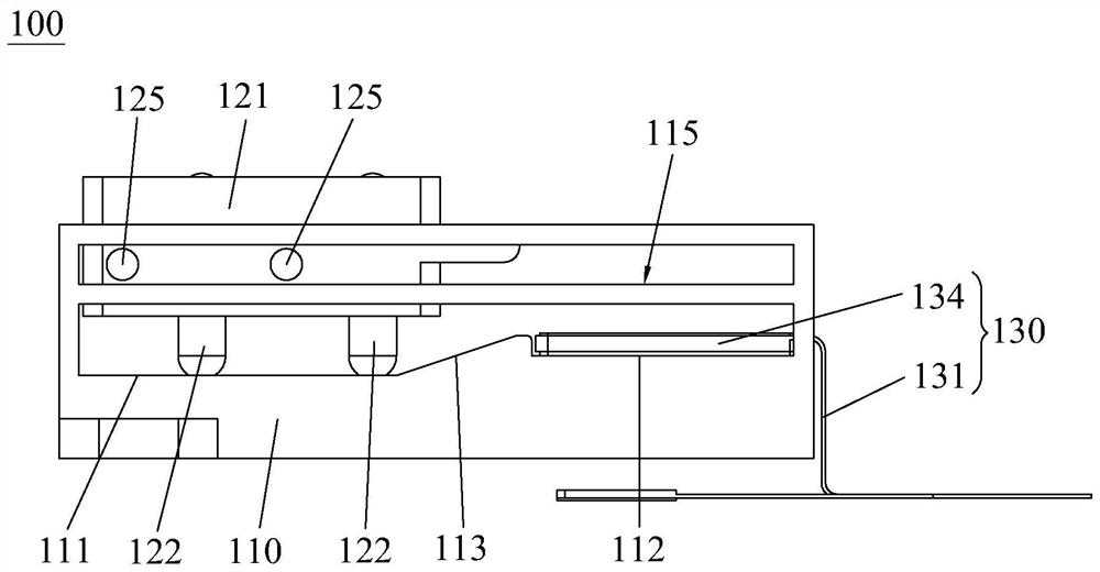
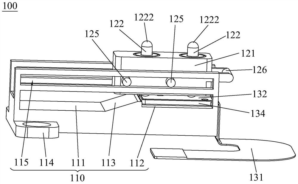
[0032] Embodiments of the present invention will now be described with reference to the drawings, in which like reference numerals represent like elements. The concealable charging connector 100 provided by the present invention is mainly applicable to the electronic device 1 using wireless charging or contact charging, but is not limited thereto.
[0033] Combine first Figure 1-Figure 5 As shown, the concealable charging connector 100 provided by the present invention includes a mounting base 110 , a needle shaft assembly 120 and an electrical connection assembly 130 . Wherein, the mounting seat 110 is used to connect to the installation site, and the mounting seat 110 is provided with a stepped and parallel first supporting surface 111, a second supporting surface 112, and connected to the first supporting surface 111, the second supporting surface The driving surface 113 between 112 , the driving surface 113 extends obliquely upward from the first supporting surface 111 t...
PUM
 Abstract
Description
Claims
Application Information
 - Generate Ideas
- Intellectual Property
- Life Sciences
- Materials
- Tech Scout
- Unparalleled Data Quality
- Higher Quality Content
- 60% Fewer Hallucinations
Browse by: Latest US Patents, China's latest patents, Technical Efficacy Thesaurus, Application Domain, Technology Topic, Popular Technical Reports.
© 2025 PatSnap. All rights reserved.Legal|Privacy policy|Modern Slavery Act Transparency Statement|Sitemap|About US| Contact US: help@patsnap.com