Tidal current energy permanent magnet generator with tooth crest temperature measurement structure

A permanent magnet generator and tidal current energy technology, which is applied in ocean energy power generation, synchronous motors with stationary armatures and rotating magnets, structural connections, etc., can solve problems such as inability to reflect the real temperature of stator teeth, and achieve accurate measurement results , the effect of a reliable reference

Active Publication Date: 2020-09-25
哈动国家水力发电设备工程技术研究中心有限公司 +1
View PDF12 Cites 0 Cited by
  • Summary
  • Abstract
  • Description
  • Claims
  • Application Information

AI Technical Summary

Problems solved by technology

[0003] The purpose of the present invention is to solve the problem that the temperature measurement at the stator tooth pressure plate cannot reflect the real temperature of the stator teeth, and to provide a tidal current energy permanent magnet generator with a tooth top temperature measurement structure

Method used


Image

  • Tidal current energy permanent magnet generator with tooth crest temperature measurement structure
  • Tidal current energy permanent magnet generator with tooth crest temperature measurement structure
  • Tidal current energy permanent magnet generator with tooth crest temperature measurement structure

Examples


specific Embodiment approach 1

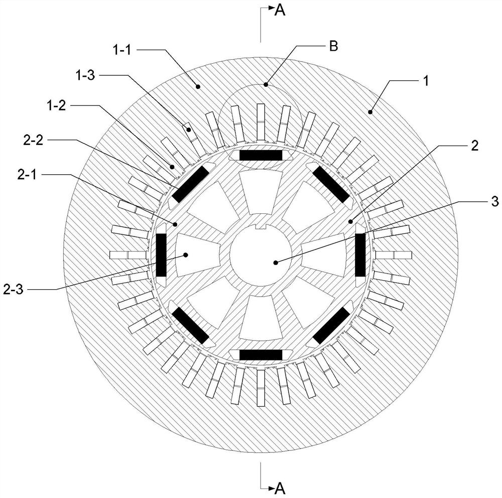
[0021] Specific implementation mode one: the following combination Figure 1 to Figure 4 This embodiment is described. The tidal current energy permanent magnet generator with tooth tip temperature measurement structure described in this embodiment includes a stator 1, a rotor 2 and a rotating shaft 3. The rotor 2 is fixed on the rotating shaft 3, and the stator 1 is arranged outside the rotor 2. , there is a radial gap between stator 1 and rotor 2;

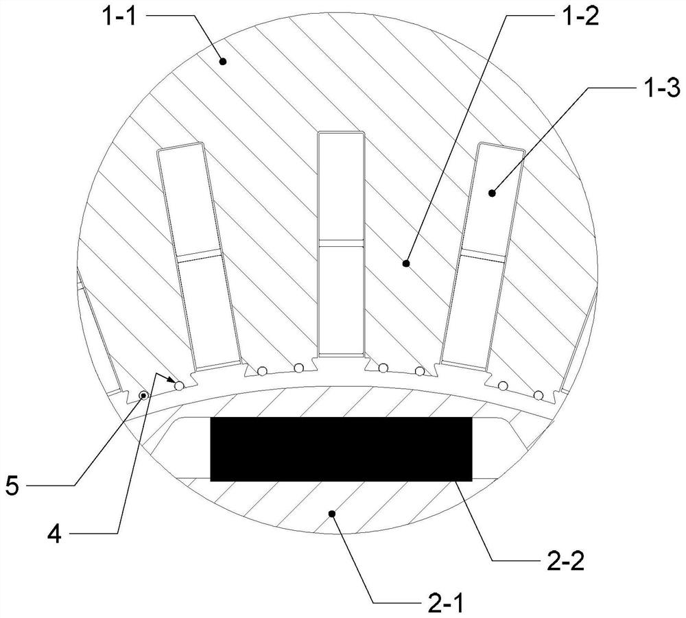
[0022] The stator 1 includes a stator core 1-1, a stator tooth 1-2 and a stator winding 1-3. The inner surface of the stator core 1-1 is uniformly distributed with 2N stator teeth 1-2 along the circumferential direction, and between two adjacent stator teeth 1-2 The stator windings 1-3 are arranged in the stator slots formed between them;

[0023] The rotor 2 includes a rotor core 2-1 and a permanent magnetic pole 2-2. The rotor core 2-1 is embedded with 2P permanent magnetic poles 2-2 along the circumferential direction. The pe...

specific Embodiment approach 2

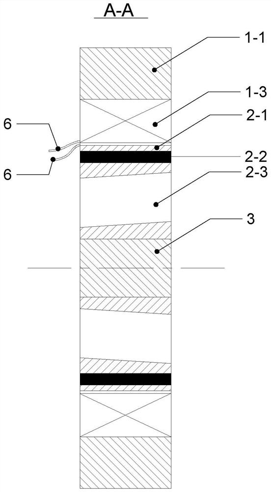
[0036] Specific Embodiment 2: This embodiment further explains Embodiment 1, and fan-shaped oblique ventilation slots 2-3 are also provided, and 2P fan-shaped oblique ventilation slots 2-3 are evenly distributed along the circumferential direction of the rotor core 2-1. The ventilation slot 2 - 3 is an axial slot passing through the rotor core, and is located between the permanent magnet pole 2 - 2 and the rotating shaft 3 .

[0037] The fan-shaped oblique ventilation slots 2-3 are axially inclined.

[0038] The stator can dissipate heat with the help of water channels in the casing, but it is difficult for the rotor to dissipate heat. Usually, there are axial ventilation slots parallel to the rotating shaft on the rotor body, but the heat dissipation effect is not good. Opening oblique ventilation grooves not only saves materials and reduces the moment of inertia, but also improves the heat dissipation effect of the rotor and effectively reduces the temperature of the rotor.


PUM


Abstract

The invention discloses a tidal current energy permanent magnet generator with a tooth crest temperature measurement structure, which belongs to the field of generators, and aims to solve the problemthat temperature measurement at a stator tooth pressing plate cannot reflect the real temperature of stator teeth. The generator comprises a stator, a rotor and a rotating shaft, the rotor is fixed onthe rotating shaft, the stator is arranged outside the rotor, and a radial gap exists between the stator and the rotor; the stator is provided with 2N stator teeth, two auxiliary grooves are formed in the tooth top of each stator tooth in the axial direction, a copper bar is embedded into each auxiliary groove, the actual resistance value output by the 4N copper bars in series when the generatoroperates is measured, and the average temperature of the tooth top of the stator is obtained according to the actual resistance value.

Description

technical field [0001] The invention relates to a temperature measurement technology of a generator, and belongs to the field of generators. Background technique [0002] Tidal current energy belongs to marine renewable energy, and it is widely distributed and inexhaustible. It has become the focus of attention of major energy countries in the world and has become the fastest-growing branch of marine energy. Tidal current generators usually use permanent magnet synchronous power generation Machine, because the slotting on the surface of the stator core will cause cogging torque, resulting in vibration and noise, and the magnetic density of the stator tooth top is high, causing serious heat generation. The traditional method of measuring the temperature of the stator tooth top is to install a thermal resistor on the stator tooth pressure plate , since the stator tooth pressure plate is located at the two axial end faces of the stator core, the thermal resistance measurement p...

Claims


Application Information

Patent Timeline
Patent Type & Authority Applications(China)
IPC IPC(8): H02K11/25H02K1/14H02K1/27H02K1/32H02K21/16F03B13/26
CPCH02K11/25H02K1/146H02K1/276H02K1/32H02K21/16F03B13/26Y02E10/30
Inventor 朱一枫李桂芬张艳竹王晓航张春莉胡刚葛旭胡金明谢雨
Owner 哈动国家水力发电设备工程技术研究中心有限公司
Why Eureka
Try Eureka