Molten metal micro-jet control valve

A technology of molten metal and electric field force, applied in the direction of additive processing, etc., can solve the problem of energizing the molten metal all the time, and achieve the effect of saving energy

Pending Publication Date: 2020-09-29
XIAMEN UNIV OF TECH
View PDF0 Cites 0 Cited by
  • Summary
  • Abstract
  • Description
  • Claims
  • Application Information

AI Technical Summary

Problems solved by technology

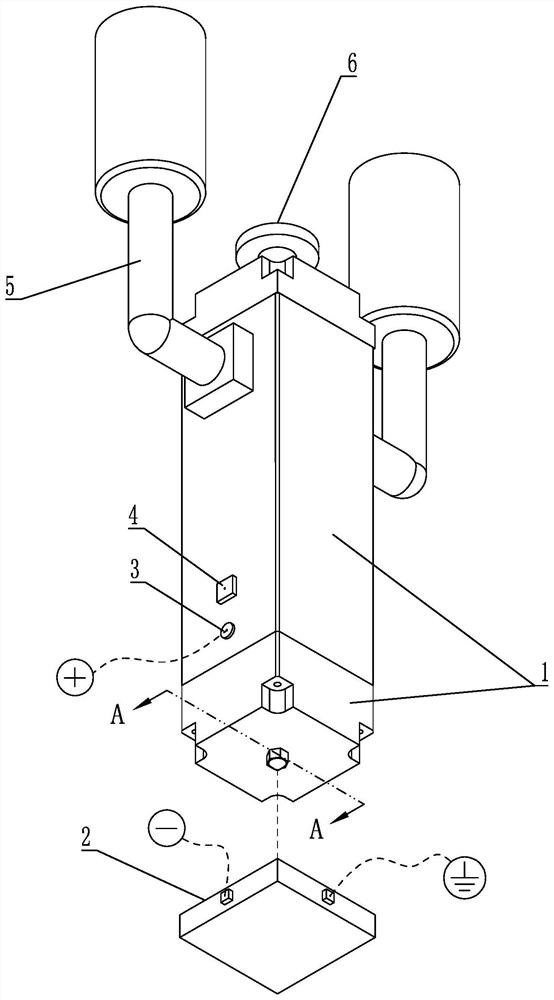
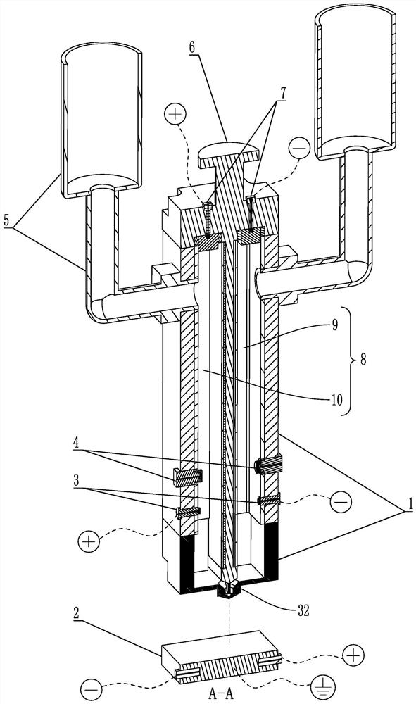
[0007] The present invention provides a micro-spray control valve for molten metal based on electric field force, aiming to improve the problem that the existing micro-spray valve needs to be constantly energized to molten metal during use

Method used


Image

  • Molten metal micro-jet control valve
  • Molten metal micro-jet control valve
  • Molten metal micro-jet control valve

Examples


Embodiment Construction

[0055]In order to make the purpose, technical solutions and advantages of the embodiments of the present invention clearer, the technical solutions in the embodiments of the present invention will be clearly and completely described below in conjunction with the accompanying drawings in the embodiments of the present invention. Obviously, the described embodiments It is some embodiments of the present invention, but not all of them. Based on the implementation manners in the present invention, all other implementation manners obtained by persons of ordinary skill in the art without creative efforts fall within the protection scope of the present invention. Accordingly, the following detailed description of the embodiments of the invention provided in the accompanying drawings is not intended to limit the scope of the claimed invention, but merely represents selected embodiments of the invention. Based on the implementation manners in the present invention, all other implementa...


PUM


Abstract

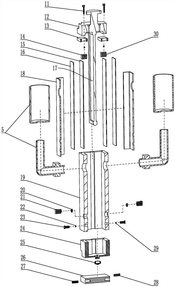
The invention provides a molten metal micro-jet control valve, and relates to the technical field of micro-jet valves. The micro-jet control valve comprises a shell mechanism internally provided witha containing cavity and a discharging opening, a partition plate mechanism used for dividing the containing cavity into a left half and a right half, a feeding mechanism supplying to-be-jetted objectsto the left half containing cavity and the right half containing cavity, a charging mechanism comprising a first charging head and a second charging head which are arranged in the left cavity and theright cavity respectively, and an electric field mechanism. The electric field mechanism comprises a first conductor and a second conductor which are arranged on the partition plate mechanism and located at the ends, away from the discharging opening, of the left cavity and the right cavity respectively. The first charging head and the second charging head are used for charging the to-be-jetted objects, so that the to-be-jetted objects in the left cavity and the right cavity respectively carry opposite charges; and the first conductor and the second conductor can be connected with a power supply and generate an electric field so as to push the charged to-be-jetted objects to move towards the discharge opening, and then the charged to-be-sprayed objects are sprayed outwards. The micro-jetcontrol valve can be charged and then jets, and the charging heads do not need to be connected with the power supply all the time during jetting.

Description

technical field [0001] The invention relates to the technical field of micro-spray valves, in particular to a micro-spray control valve for liquid metal based on electric field force. Background technique [0002] Electromagnetic force micro-spray valve is a special micro-spray valve that drives liquid injection through electromagnetic force by energizing molten metal and then adding a magnetic field. It can be applied to additive manufacturing, ie 3D printing. At present, there are two main types of micro-spray valves driven by electromagnetic force: [0003] The first type is fixed on the valve body by a permanent magnet to generate a magnetic field. Under the action of the magnetic field, the energized molten metal will be subjected to a downward Lorentz force, thereby ejecting metal droplets; [0004] The second type is similar to the first type, that is, a coil is wound on the valve body, and a magnetic field is generated after an alternating current is passed through...

Claims


Application Information

Patent Timeline
Patent Type & Authority Applications(China)
IPC IPC(8): B22F3/115B33Y50/02B33Y30/00
CPCB22F3/115B22F2999/00B33Y30/00B33Y50/02B22F2202/06
Inventor 李志红黄博罗志伟
Owner XIAMEN UNIV OF TECH
Why Eureka
Try Eureka