Cold galvanizing coating equipment and process of low carbon steel wire

A low-carbon steel wire, cold galvanizing technology, which is applied in metal material coating process, hot-dip galvanizing process, coating, etc., can solve the problem that the low-carbon steel wire cannot be polished and degreased, and the quality of low-carbon steel wire cold galvanizing is affected , Can not automatically realize intermittent feeding and other problems, to achieve the effect of easy replacement and cleaning, good cleaning effect, and guaranteed cleaning effect

Active Publication Date: 2020-09-29
马鞍山市剑群金属制品有限公司
View PDF10 Cites 2 Cited by
  • Summary
  • Abstract
  • Description
  • Claims
  • Application Information

AI Technical Summary

Problems solved by technology

[0003] Most of the cold-dip galvanized coating equipment for low-carbon steel wire currently on the market is relatively simple when loading materials. Personnel control intermittent feeding or do not use intermittent feeding, which will affect the quality of low-carbon steel wire cold galvanizing. When some low-carbon steel wire cold-dip galvanizing coating equipment is used, it cannot properly treat the outer side of low-carbon steel wire. Effective grinding and degreasing treatment will lead to insufficient pre-treatment of low-carbon steel wire, which will affect the quality of cold-galvanized low-carbon steel wire in the later stage. Therefore, a cold-dip galvanized coating for low-carbon steel wire is proposed to solve the above problems Equipment and process

Method used


Image

  • Cold galvanizing coating equipment and process of low carbon steel wire
  • Cold galvanizing coating equipment and process of low carbon steel wire
  • Cold galvanizing coating equipment and process of low carbon steel wire

Examples


Embodiment 1

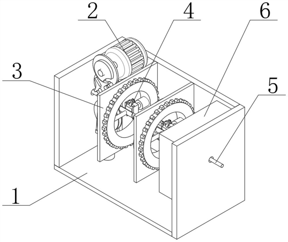
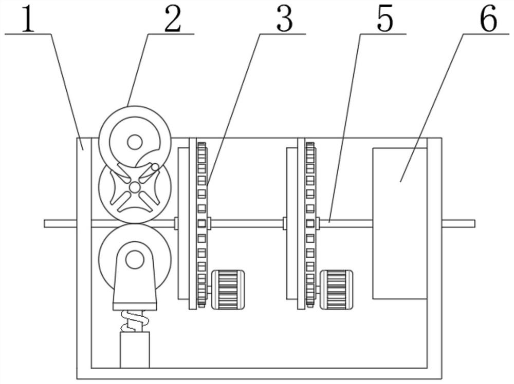
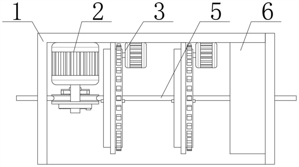
[0029] Example 1: See Figure 1-6 , the present invention provides a technical solution:

[0030] A cold galvanized coating equipment for low-carbon steel wire, including a shell 1, an intermittent feeding device 2, a rotating cleaning device 3, a detachable cleaning block structure 4, a low-carbon steel wire 5 and an electrolytic device 6, the inside of the shell 1 is from From left to right, intermittent feeding device 2, rotating cleaning device 3 and electrolytic equipment 6 are installed in sequence. Low carbon steel wire 5 runs through the inner side of shell 1, intermittent feeding device 2, rotating cleaning device 3 and electrolytic equipment 6, and rotating cleaning device 3 A detachable cleaning block structure 4 is installed on the inner side, and one side of the detachable cleaning block structure 4 is attached to a low carbon steel wire 5 .

[0031]The intermittent feeding device 2 includes a feeding motor 201, a chassis 202, a turntable 203, a cylindrical pin 2...


PUM


Abstract

The invention relates to the technical field of metal surface treatment, in particular to cold galvanizing coating equipment and process of a low carbon steel wire. The equipment comprises a housing,an intermittent feeding device, a rotary cleaning device, a detachable cleaning block structure, the low carbon steel wire and electrolyzing equipment. The intermittent feeding device, the rotary cleaning device and the electrolyzing equipment are successively mounted on the inner side of the housing from left to right. The low carbon steel wire penetrates the housing, the intermittent feeding device, the rotary cleaning device and the electrolyzing equipment. The detachable cleaning block structure is mounted on the inner side of the rotary cleaning device, and one side of the detachable cleaning block structure is attached to the low carbon steel wire. According to the invention, by arranging the rotary cleaning device, the device can rotate at 360 degrees effectively to be cleaned and used, so that the cleaning effect to the outer side of the low carbon steel wire can be guaranteed effectively, and therefore, the cold galvanizing effect is further guaranteed effectively.

Description

technical field [0001] The invention relates to the technical field of metal surface treatment, in particular to a low-carbon steel wire cold galvanizing coating equipment and process. Background technique [0002] Low-carbon steel wire is also called iron wire. Low-carbon steel wire is a kind of metal wire drawn from low-carbon steel. Iron wire has different components according to its use. The components it contains are: iron, cobalt, nickel, copper, carbon, Zinc, and other elements, cold-dip galvanizing is also called electro-galvanizing, which uses electrolytic equipment to put the pipe fittings into a solution composed of zinc salt after degreasing and pickling, and connects the negative electrode of the electrolytic equipment, and places them on the opposite side of the pipe fittings. The zinc plate is connected to the positive pole of the electrolysis equipment and connected to the power supply. A layer of zinc will be deposited on the pipe fittings by using the direc...

Claims


Application Information

Patent Timeline
IPC IPC(8): C23C2/02C23C2/06C23C2/38B08B1/02B24B5/38B24B27/00B24B47/16B24B41/06B24B47/12
CPCC23C2/02C23C2/06C23C2/38B24B5/38B24B27/003B24B47/16B24B41/067B24B47/12B08B1/20
Inventor 贾英健
Owner 马鞍山市剑群金属制品有限公司
Why Eureka
Try Eureka