Drilling machine propulsion control system and method and drill rod

A technology of propulsion control and drill pipe, which is applied to the automatic control system of drilling, drilling equipment, earth-moving drilling, etc., can solve the problems of difficult control of manual valve, difficult installation and maintenance, delay of hydraulic valve control, etc., to avoid Control the delay problem, reduce the processing cost, and control the effect of high efficiency

Active Publication Date: 2020-09-29
CHINA RAILWAY CONSTR HEAVY IND
View PDF6 Cites 2 Cited by
  • Summary
  • Abstract
  • Description
  • Claims
  • Application Information

AI Technical Summary

Problems solved by technology

Among them, hydraulic control and manual control both involve control components such as various control valves. The number and types of parts involved are large, and installation and maintenance are difficult and costly.
In addition, the hydraulic valve has the defect of control delay, and the manual operation of the valve is difficult to control, resulting in low control efficiency of the existing drilling rig

Method used


Image

  • Drilling machine propulsion control system and method and drill rod
  • Drilling machine propulsion control system and method and drill rod
  • Drilling machine propulsion control system and method and drill rod

Examples


Embodiment Construction

[0036] The following will clearly and completely describe the technical solutions in the embodiments of the present invention with reference to the accompanying drawings in the embodiments of the present invention. Obviously, the described embodiments are only some, not all, embodiments of the present invention. Based on the embodiments of the present invention, all other embodiments obtained by persons of ordinary skill in the art without making creative efforts belong to the protection scope of the present invention.

[0037] In order to enable those skilled in the art to better understand the solution of the present invention, the present invention will be further described in detail below in conjunction with the accompanying drawings and specific embodiments.

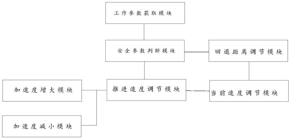
[0038] Please refer to figure 1 , figure 1 It is a simplified structural diagram of a drilling rig propulsion control system provided by a specific embodiment of the present invention.

[0039] The embodiment of t...


PUM


Abstract

The invention discloses a drilling machine propulsion control system. The system comprises a working parameter module, a safety parameter judgment module and a propelling speed adjusting module; current working parameters are acquired by the working parameter module; whether the current working parameters are greater than preset safety parameters or not is judged by the safety parameter judgment module, and if so, a drill rod is controlled to return; if not, the current working parameters and the preset working parameters are compared; finally, whether the current working parameters are greater than preset working parameters or not is judged by the propelling speed adjusting module, and if yes, on the premise that the current propelling speed is greater than the preset propelling speed, the current propelling speed is reduced, and the drill rod is controlled to propel at the current propelling speed; and if not, the current propelling speed is increased, and the drill rod is controlledto propel at the current propelling speed. Therefore, an existing hydraulic control system or an existing manual control system is replaced by an electric control mode, the problem of control delay is avoided, the number of related parts is small, the control efficiency is high, and the production cost is low. The invention further discloses a drilling machine comprising the drilling machine propulsion control system and a drilling machine propulsion control method.

Description

technical field [0001] The invention relates to the technical field of mining equipment, in particular to a drilling rig propulsion control system and method. The invention also relates to a drilling rig comprising a drilling rig propulsion control system. Background technique [0002] In the construction of unfavorable geological tunnels such as weak surrounding rocks, drilling rigs are mostly used for long-distance advanced geological prediction, outburst prevention, grouting and water sealing, pipe sheds, anchor cables, anchor rods and other methods to ensure tunnel construction. Existing drilling rigs mostly use hydraulic valves or manual control valves to control the advancing speed of the drill pipe. Among them, hydraulic control and manual control both involve control components such as various control valves. The number and types of parts involved are large, and installation and maintenance are difficult and costly. In addition, the hydraulic valve has the defect o...

Claims


Application Information

Patent Timeline
Patent Type & Authority Applications(China)
IPC IPC(8): E21B44/00E21B44/02
CPCE21B44/00E21B44/02
Inventor 蔡志山方双普汤秋萍陈姣元蔡立果
Owner CHINA RAILWAY CONSTR HEAVY IND
Why Eureka
Try Eureka