Supercharge Your Innovation With Domain-Expert AI Agents!

Chain drive mechanism

A chain transmission mechanism and chain technology, applied in transmission devices, belts/chains/gears, mechanical equipment, etc., can solve torque transmission blockage, disengagement, and inability to maintain the first engaging part 8 and the second engaging part 9 Problems such as the snapping state, to achieve the effect of suppressing the impact sound and reducing the cost of raw materials

Inactive Publication Date: 2020-09-29
TSUBAKIMOTO CHAIN CO
View PDF2 Cites 0 Cited by
  • Summary
  • Abstract
  • Description
  • Claims
  • Application Information

AI Technical Summary

Problems solved by technology

[0009] Although the overload protection device known in this patent document 2, when the torque transmitted between the sprocket 4 and the rotating shaft (transmission shaft 2) is smaller than the allowable torque, the convex shape of the second engaging member 9 The engaging surface 12 is fully inserted into the concave engaging surface 11 of the first engaging member 8 due to the force of the elastic member (elastic body 10), and the rotating shaft (transmission shaft 2) and the sprocket 4 are integrally rotated, However, when the torque transmitted between the sprocket 4 and the rotating shaft (transmission shaft 2) exceeds the allowable torque, the elastic member (elastic body 10) cannot maintain the relationship between the first engaging member 8 and the second engaging member 9. engaged state, so that the concave engaging surface 11 is disengaged from the convex engaging surface 12, and the torque transmission is blocked

Method used


Image

  • Chain drive mechanism
  • Chain drive mechanism
  • Chain drive mechanism

Examples


Embodiment Construction

[0040] Next, a chain transmission mechanism according to an embodiment of the present invention will be described based on the drawings.

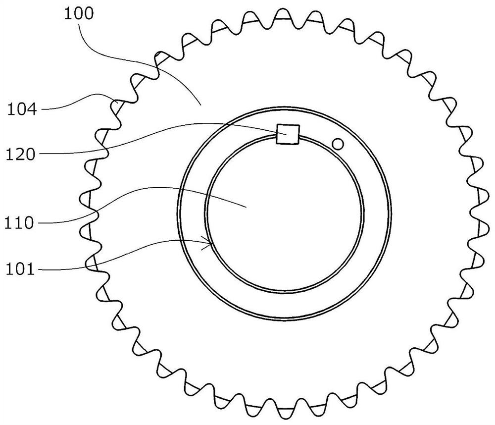
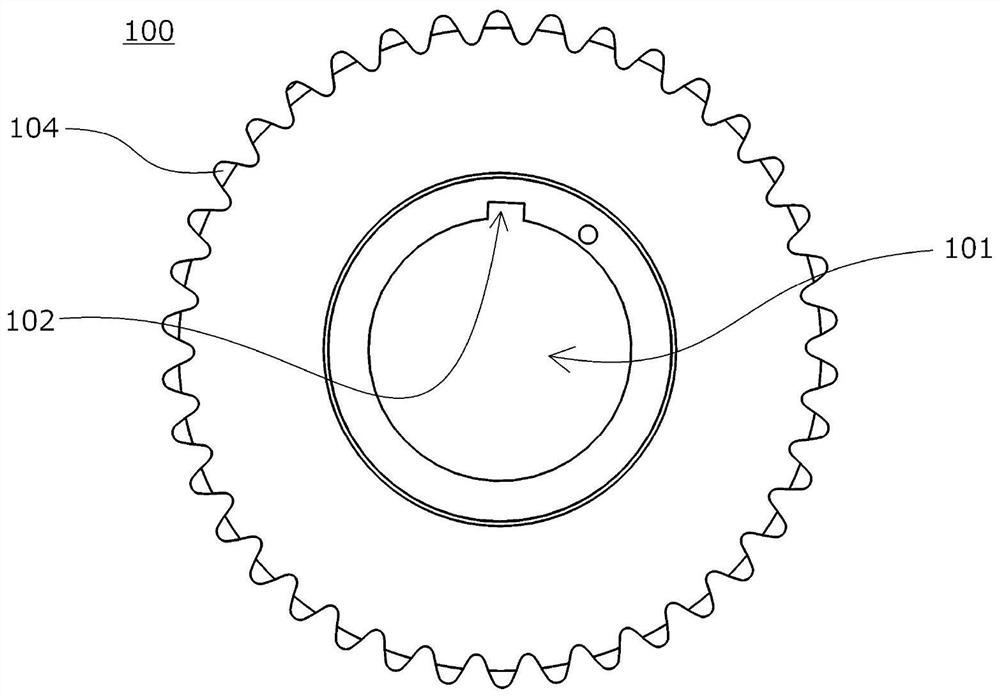
[0041] Such as Figure 1 to Figure 3 As shown, the chain transmission mechanism which is an embodiment of the present invention has a rotating shaft 110 , a sprocket 100 having a shaft hole 101 pierced by the rotating shaft 110 , and a chain (not shown) wound around the sprocket 100 .

[0042] On the inner peripheral surface of the shaft hole 101 , a groove-shaped rotation transmission groove 102 is provided along the opening direction of the shaft hole 101 .

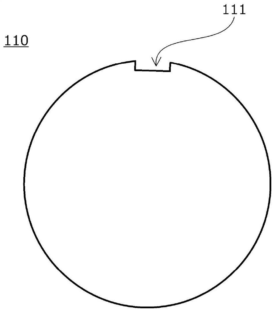
[0043] On the outer peripheral surface of the rotating shaft 110 , a groove-shaped receiving groove 111 is provided along the central axis of the rotating shaft 110 , and the receiving groove 111 and the rotation transmission groove 102 are formed to have equal circumferential widths.

[0044] In the receiving groove 111, a rotation transmission member 120 made of an elastic member ...


PUM


Abstract

The invention provides a simple-structured chain drive mechanism that can reduce the noise generated when the chain sits on the sprocket, prevent deterioration of power transmission efficiency, and reduce wear of the sprocket and chain. The chain drive mechanism includes a rotating shaft (110), a sprocket (100) having a shaft hole (101), and a chain. The shaft hole (101) is provided with a rotation transmitting groove (102) on an inner circumferential surface thereof. The rotating shaft (110) is provided with a rotation transmitting member (120) that engages with the rotation transmitting groove (102). The rotation transmitting member (120) is configured to be capable of relative sliding movement at least in a circumferential direction of the rotating shaft (110) and capable of restoring relative positions of the rotating shaft (110) and the sprocket (100).

Description

technical field [0001] The present invention relates to a chain transmission mechanism having a plurality of sprockets and a chain wound around the sprockets. Background technique [0002] As a chain transmission mechanism, a chain transmission mechanism using a chain such as a plurality of sprockets, a roller chain wound around the sprockets, or a silent chain is known, and is widely used for transmission of driving force, synchronization of rotation timing, rotation speed or Changes in torque, etc. [0003] For example, a silent chain is generally constructed by flexibly connecting many link plates having a pair of teeth and a pair of pin holes with connecting pins inserted into each pin hole, and the chain transmission mechanism is configured to The silent chain is endlessly wound around a plurality of sprockets so that the teeth of the link plates mesh with the teeth of the sprockets to transmit rotation. [0004] In such a chain transmission mechanism, when each link ...

Claims


Application Information

Patent Timeline
Patent Type & Authority Applications(China)
IPC IPC(8): F16H55/30F16H7/06
CPCF16H7/06F16H55/30F16H2055/306F16H55/08F16H57/0006
Inventor 角野贵大
Owner TSUBAKIMOTO CHAIN CO
Features
  • R&D
  • Intellectual Property
  • Life Sciences
  • Materials
  • Tech Scout
  • Unparalleled Data Quality
  • Higher Quality Content
  • 60% Fewer Hallucinations
Learn More