
Bunching SAR compressed sensing imaging method based on approximate observation matrix

An observation matrix and compressed sensing technology, applied in the field of radar, can solve the problems of high computational complexity and storage cost, less application range, and low efficiency, and achieve the effect of reducing computational complexity, storage memory, and wide range

Active Publication Date: 2020-09-29
NANJING UNIV OF POSTS & TELECOMM
View PDF4 Cites 3 Cited by
  • Summary
  • Abstract
  • Description
  • Claims
  • Application Information

AI Technical Summary

Problems solved by technology

In the existing published literature, many experts and scholars propose a CS-based framework by sampling data in the frequency domain, but these works are actually not applicable to CS-SAR systems that wish to sample in the time domain; in addition , in most literatures, a more general CS-SAR model is proposed by precisely discretizing the SAR observation function into an observation matrix and solving it directly by CS
All these works fully demonstrate that CS-SAR does have some unique advantages compared to conventional SAR imaging methods, such as relaxation of the required measurements, reduction of sidelobes, and further suppression of noise, however, in all applications Among them, serious disadvantages have been observed: Compared with traditional methods, the computational complexity and storage cost of CS-SAR model are much higher, so it is very inefficient to apply it to large scene conditions, and related literature regards MF (matching filtering) and CS to form a new CS-SAR imaging method, which reduces the computational complexity and storage cost, but this method is based on the MF imaging process, which is relatively simple and has less application range

Method used


Image

  • Bunching SAR compressed sensing imaging method based on approximate observation matrix
  • Bunching SAR compressed sensing imaging method based on approximate observation matrix
  • Bunching SAR compressed sensing imaging method based on approximate observation matrix

Examples


Embodiment Construction

[0040] Embodiments of the present invention will be disclosed in the following diagrams. For the sake of clarity, many practical details will be described together in the following description. It should be understood, however, that these practical details should not be used to limit the invention. That is, in some embodiments of the invention, these practical details are not necessary.

[0041] In addition, the technical solutions of the various embodiments can be combined with each other, but it must be based on the realization of those skilled in the art. When the combination of technical solutions is contradictory or cannot be realized, it should be considered that the combination of technical solutions does not exist , nor within the scope of protection required by the present invention.

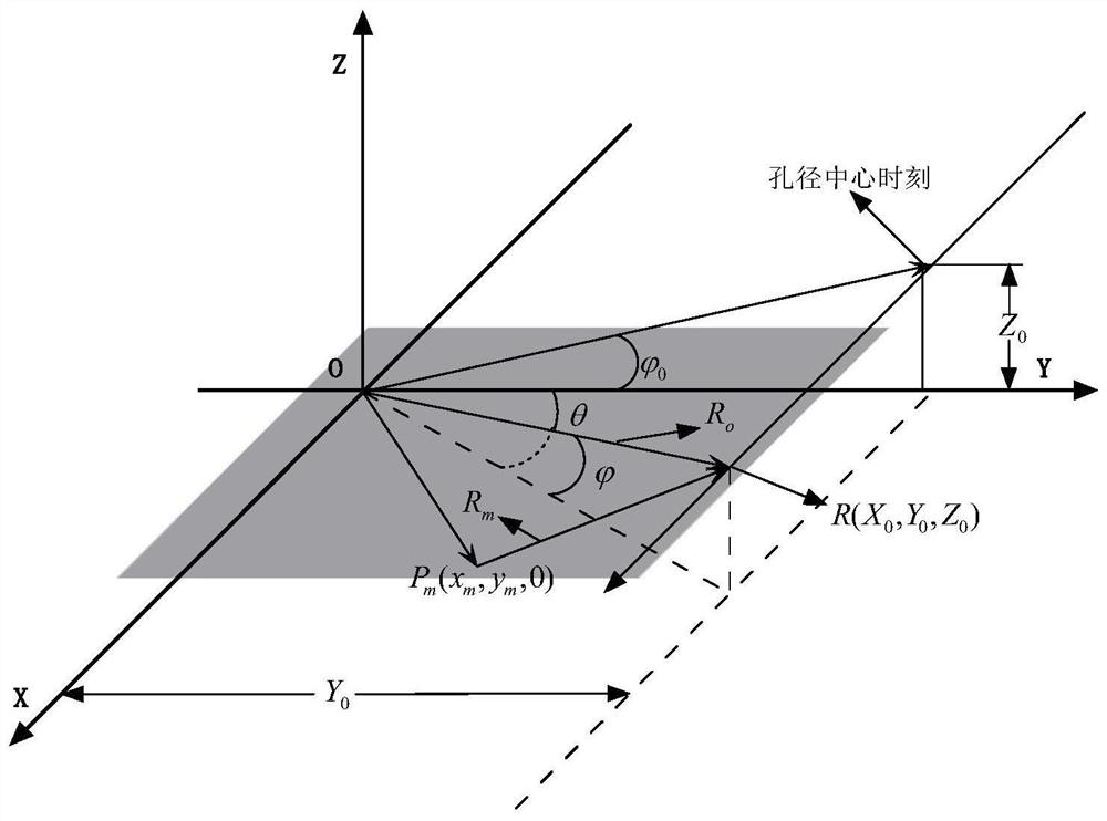
[0042] Such as figure 2 The spatial geometric relationship diagram of spotlight SAR data acquisition is shown, the origin of the coordinate system O is the origin of the coordinates,...


PUM


Abstract

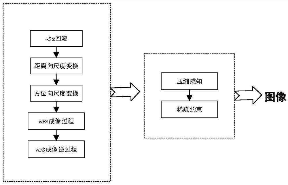
The invention relates to a bunching SAR compressed sensing imaging method based on an approximate observation matrix. The bunching SAR compressed sensing imaging method comprises the following steps:1, obtaining a matrix form of distance-direction scale transformation based on a polar coordinate format algorithm of scale transformation; 2, obtaining a matrix form of azimuth scale transformation based on the polar coordinate format algorithm of scale transformation; 3, deriving a matrix expression form of a polar coordinate format algorithm imaging process according to results of the step 1 and the step 2; 4, deriving a signal model of an inverse imaging process according to a signal model of a radar projection matrix obtained in the step 3; and 5, constructing a CS reconstruction model byusing a PFA imaging process and an inverse imaging process obtained in the above steps and an iterative threshold shrinkage algorithm based on the approximate observation matrix. According to the method, sparse constraint is carried out on the PFA imaging process, the application range of PFA imaging in the SAR field is wider, and compared with a traditional accurate measurement matrix, the calculation complexity and the storage memory are greatly reduced.

Description

technical field [0001] The invention belongs to the field of radar technology, and in particular relates to a spotlight SAR compressed sensing imaging method based on an approximate observation matrix. Background technique [0002] Traditional synthetic aperture radar (Synthetic Aperture Radar, SAR) usually transmits and receives signals based on linear tracks, and realizes all-day and all-weather detection and imaging after coherent processing of echoes. In a SAR system, the radar transmits a series of pulses along its path and receives the echoes scattered from the target as raw data. Traditionally, the reconstruction of the scene is achieved by focusing the image based on the Polar Format Algorithm (PFA), which is efficient, but SAR imaging with increasing resolution and coverage requires more and more measurements, storage and downlink Bandwidth, however, is often hindered by current system hardware for such high-dimensional applications. [0003] In recent years, the ...

Claims


Application Information

Patent Timeline
IPC IPC(8): G01S13/90G06F17/14G06F17/16
CPCG01S13/9011G01S13/9094G06F17/142G06F17/16
Inventor 王昕乔玲
Owner NANJING UNIV OF POSTS & TELECOMM
Learn More