
Manufacturing method of two-in-one structure inductor with air gap on side surface

A manufacturing method and side surface technology, applied in the direction of inductor/transformer/magnet manufacturing, transformer/inductor core, transformer/inductor cooling, etc. Interference, small overload capacity of round copper wire, etc., to achieve the effect of strong anti-electromagnetic interference performance, small DC loss and good conduction effect

Active Publication Date: 2021-11-30
GUANGZHOU DELOOP ELECTRONICS DEVICES
View PDF6 Cites 0 Cited by
  • Summary
  • Abstract
  • Description
  • Claims
  • Application Information

AI Technical Summary

Problems solved by technology

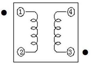
[0002] For the electrical principle and magnetic structure of the two-in-one inductor products currently on the market, please refer to figure 1 and figure 2 , this structure is to open an air gap on the front of the magnetic core, and the position of the air gap is as follows image 3 As shown, the magnetic core of this structure is assembled by two separate products. Each product uses a pair of E-shaped magnetic materials. The product is large and inconvenient to install. It does not meet the current trend of thin, light and miniaturized electronic components.
Moreover, the inductor in the prior art uses a round copper wire wound coil as a conductor, and the D.D.R. is large, resulting in increased DC loss
In addition, due to the small overload capacity of the round copper wire and the circular cross-section, the distance between the wires and the layers during the winding process is large, resulting in waste of space and large distributed capacitance, large leakage inductance, resulting in poor EMC performance and adverse effects on peripheral components. cause electromagnetic interference with equipment
For a long time, domestic technicians wanted to solve the above problems, but they could not solve the existing problems at the same time. Either the product cost was too high, the competitiveness declined, or the problem of large product volume could not be solved.

Method used


Image

  • Manufacturing method of two-in-one structure inductor with air gap on side surface
  • Manufacturing method of two-in-one structure inductor with air gap on side surface
  • Manufacturing method of two-in-one structure inductor with air gap on side surface

Examples


Embodiment 1

[0053] The manufacturing method of the two-in-one structure inductor with an air gap on the side surface of this embodiment includes the following steps:

[0054] (1) Preparation of accessories:

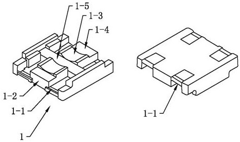
[0055] Ⅰ. Injection molding of the base: Use the injection molding machine to produce the base raw materials. The base has four electrode slots and a partition wall in the middle. The two electrode slots on the same side of the partition form a group of electrode slots. Each group There is a cushion seat between the two electrode slots of the electrode slot. The cushion seat is provided with an arc-shaped concave surface. The outer side of the arc-shaped concave surface has a magnetic core adhesive area. The base structure sees image 3 ;

[0056] Ⅱ. Electrode forming: The cut metal sheet is punched and formed to form an electrode. The electrode is in the shape of a U-shaped clip and has a bent Z-shaped extension piece. The electrode is used as a conductive carrier connecting the pr...

Embodiment 2

[0071] The main technical solution of this embodiment is basically the same as that of Embodiment 1, and the features not explained in this embodiment are explained in Embodiment 1, and will not be repeated here. It also includes the electrical test step (9), testing the inductance value, current resistance value and withstand voltage degree, among which, ① test inductance condition: 100KHz 0.25V, inductance value 1.0μH±20%; ② test DC resistance condition: at 20 ℃ D.C.R. value is less than 7.0 mΩ; ③ withstand voltage test: coil-core, DC voltage 120V, current 2 mA, time 2 seconds. Other electrical characteristics can be tested according to customer needs.


PUM

PropertyMeasurementUnit
electrical resistanceaaaaaaaaaa

Abstract

The invention discloses a method for manufacturing an inductor with a two-in-one structure with an air gap on the side surface. The base has four electrode grooves, which can facilitate electrode installation without using an additional positioning device for positioning. The Z-shaped extension sheet at the end of the coil is close to the electrode so that the extension sheet wraps the end of the coil and is pressed tightly with a jig tool. The extension sheet of the electrode is arranged in a Z shape so that the extension sheet just wraps the end of the coil, and the wrapping of the two is welded again to achieve a conductive effect Better, effectively reduce loss. Compared with the inductor with an air gap on the front surface, the two-in-one structure inductor with an air gap on the side surface prepared by the manufacturing method of the present invention has a compact overall structure, small volume and good performance. The preparation method of the invention is simple in operation and convenient in assembly, has formed an independent complete side surface with air gaps during production, and has high work efficiency.

Description

technical field [0001] The invention relates to the technical field of inductor manufacturing, in particular to a manufacturing method of an inductor with a two-in-one structure with an air gap on the side surface. Background technique [0002] For the electrical principle and magnetic structure of the two-in-one inductor products currently on the market, please refer to figure 1 and figure 2 , this structure is to open an air gap on the front of the magnetic core, and the position of the air gap is as follows image 3 As shown, the magnetic core of this structure is assembled by two separate products. Each product uses a pair of E-shaped magnetic materials. The product is large and inconvenient to install. It does not meet the current trend of thin, light and miniaturized electronic components. Moreover, the inductor in the prior art uses a round copper wire wound coil as a conductor, and the D.D.R. is large, resulting in increased DC loss. In addition, due to the small...

Claims


Application Information

Patent Timeline
Patent Type & Authority Patents(China)
IPC IPC(8): H01F27/30H01F27/29H01F27/24H01F27/28H01F27/34H01F27/36H01F27/08H01F41/00
CPCH01F27/08H01F27/24H01F27/2823H01F27/2876H01F27/29H01F27/306H01F27/346H01F41/00
Inventor 汪洋汪民许玉方陈燕凌
Owner GUANGZHOU DELOOP ELECTRONICS DEVICES
Learn More