Agricultural field stirring fertilizer applicator
A fertilizer spreader, field technology, applied in fertilization device, mixer with rotating stirring device, application, etc., can solve the problems of wasting fertilizer, sore arms, affecting the growth of crops, etc., and achieve the effect of improving work efficiency
- Summary
- Abstract
- Description
- Claims
- Application Information
AI Technical Summary
Problems solved by technology
Method used
Image

Examples
Embodiment 1
[0059] A kind of agricultural field mixing and fertilizing machine, such as figure 1 As shown, it includes a support frame 1, a wheel 2, a cover 3, a handle 4, a stirring and unloading mechanism 5, a vibration spreading mechanism 6 and a motor 8, and the left and right sides of the support frame 1 are rotatably connected with wheels 2. The upper part of the support frame 1 is connected with a vibration spreading mechanism 6, the top of the support frame 1 is connected with a stirring and discharging mechanism 5, the stirring and discharging mechanism 5 is connected with the vibration spreading mechanism 6, and the rear side of the top of the support frame 1 is connected with a motor 8 and a motor 8 The output shaft is connected with the stirring and unloading mechanism 5, the right side of the support frame 1 is connected with a handle 4, and the top of the agitating and unloading mechanism 5 is covered with a cover 3.
[0060] When people need to fertilize, first the lid 3 is...
Embodiment 2
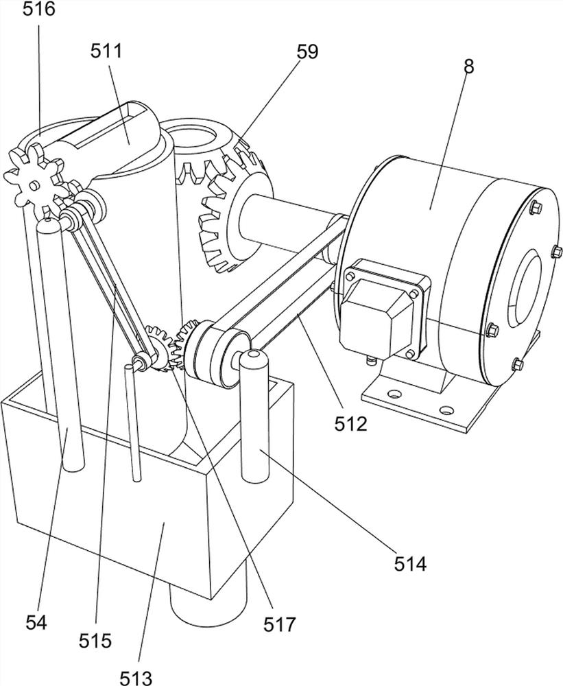
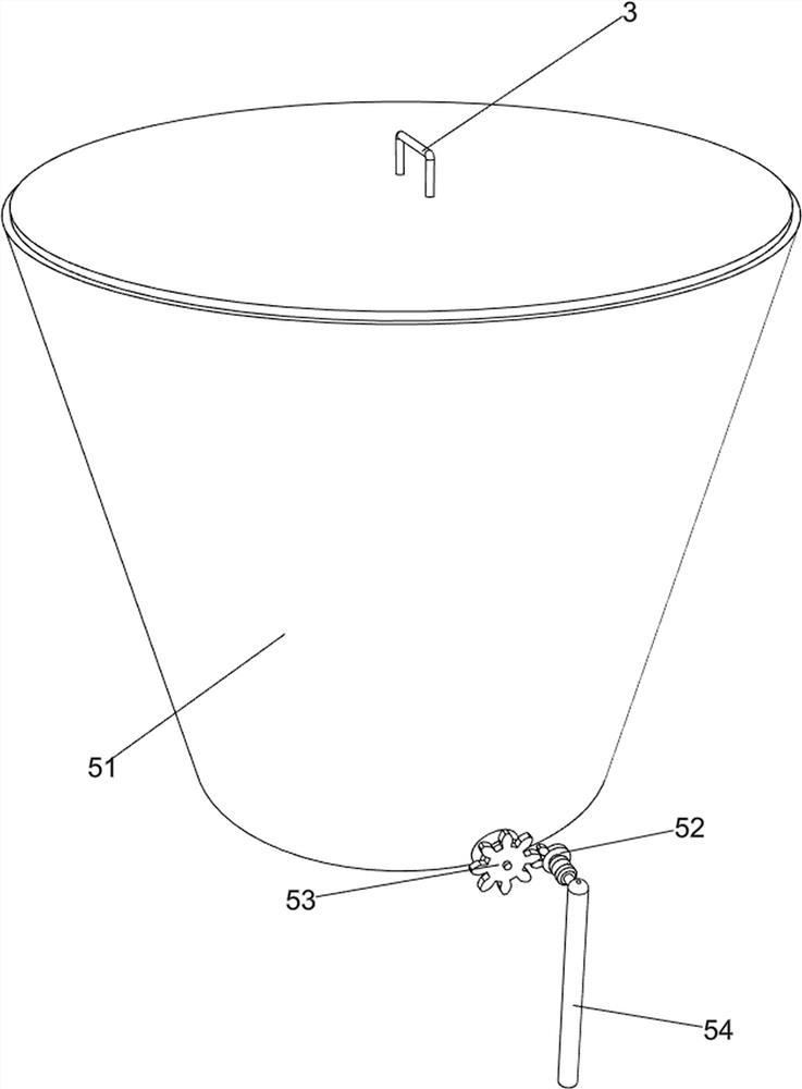
[0062] On the basis of Example 1, such as Figure 2-4As shown, the stirring and blanking mechanism 5 includes a charging barrel 51, a half gear 52, a spur gear 53, a first support rod 54, a first stirring rod 55, a second stirring rod 56, an intermittent blanking plate 57, and a third stirring rod. Rod 58, steering gear 59, driving rod 510, rotating feed shaft 511, first belt assembly 512, mixing material placement box 513, second support rod 514, second belt assembly 515, flow pipe 516 and bevel gear assembly 517, The middle part on the right side of the top of the support frame 1 is connected with a first support rod 54; The rod 514 is rotatably connected with a rotating shaft, the first belt assembly 512 is connected between the rotating shaft and the output shaft of the motor 8, and the rear part of the right side of the top of the support frame 1 is rotatably connected with a rotating shaft, and the rotating shaft is located between the second support rod 514 and the seco...
Embodiment 3
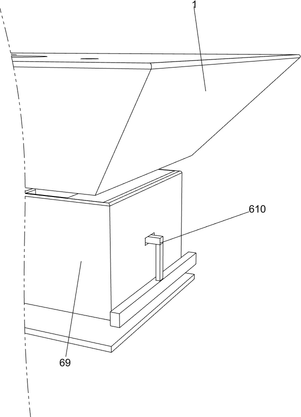
[0065] On the basis of Example 2, such as Figure 5-7 As shown, the vibration spreading mechanism 6 includes a belt rotating rod 61, a third support rod 62, a third belt 63, a drive plate 64, a first spring 65, a second spring 66, a connecting block 67, a translation block 68, a shaking lower Material box 69, fixed sliding bar 610, sliding plate 611, moving plate 612 and moving post 613, support frame 1 upper rear side is connected with fixed sliding bar 610, fixed sliding bar 610 and support frame 1 top are slidably connected with shaking Feed box 69, the bottom of shaking feed box 69 is uniformly provided with round holes, the bottom of mixing material placement box 513 is located in the shake feed box 69, and the left and right parts of the upper front side of the support frame 1 are connected with translation blocks 68, and the translation blocks 68 are up and down. Both sides are slidably connected with a moving post 613, a sliding plate 611 is connected between the movin...
PUM
 Abstract
Description
Claims
Application Information