Air duct structure of dishwasher
A technology for dishwashers and air ducts, which is applied in the field of air duct structure of dishwashers, and can solve problems such as mildew, corrosion of fans, and small air volume of drying fans.
- Summary
- Abstract
- Description
- Claims
- Application Information
AI Technical Summary
Problems solved by technology
Method used
Image
Examples
Embodiment 1
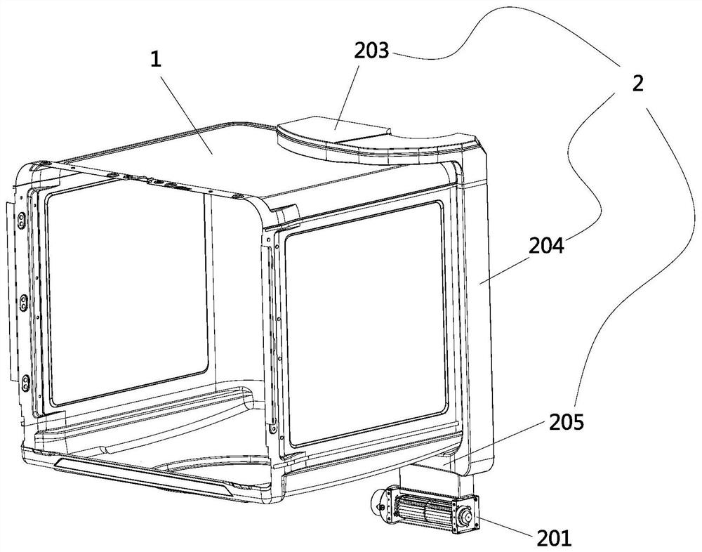
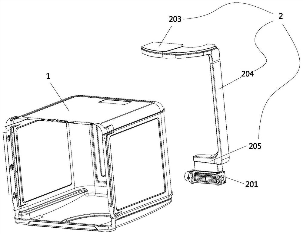
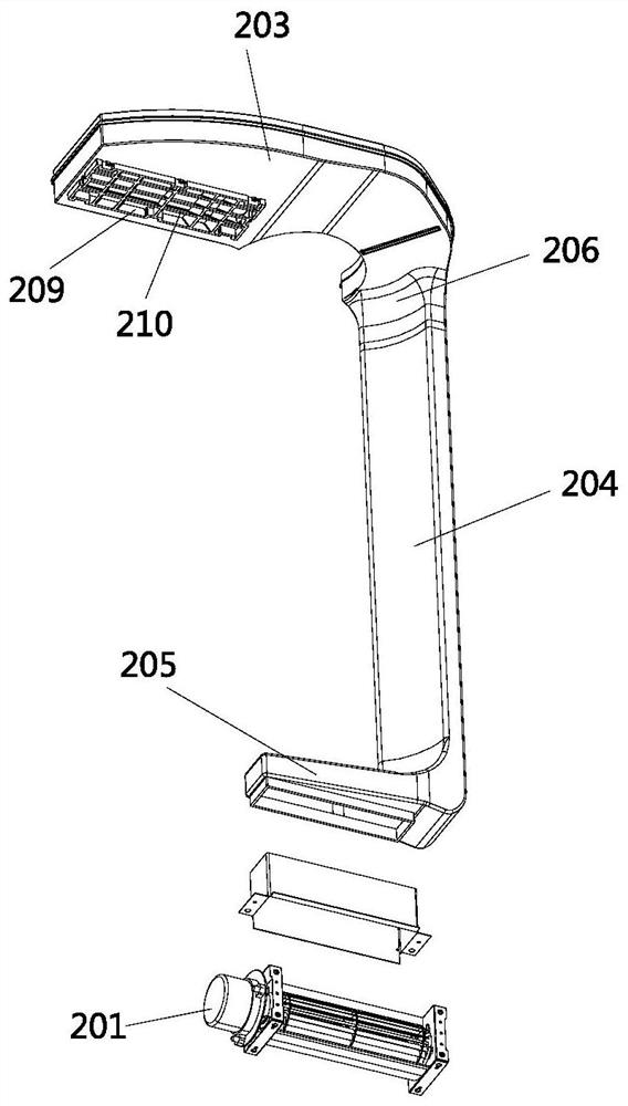
[0123] Such as figure 1 and figure 2 As shown, the air duct structure of a dishwasher described in this embodiment includes a first air duct 2 and a second air duct 3 communicating with the accommodating chamber 1 of the dishwasher; the first air duct 2 A fan unit 201 is provided; under the action of the fan unit 201, the gas in the accommodating chamber 1 is discharged from the dishwasher through the first air duct 2; the gas outside the accommodating chamber 1 is discharged from the dishwasher The second air duct 3 enters the accommodation chamber 1; the first air duct 2 is also provided with an anti-backflow structure to prevent water or steam from flowing backward from the accommodation chamber 1 along the air duct.
[0124] In the present invention, by setting an air duct structure that fits into the dishwasher storage chamber 1 and the area of the air flow area in the air duct changes, the air flow can quickly pass through the air duct, enter the first air duct 2 fro...
Embodiment 2
[0126] Such as Figure 1 to Figure 4 As shown, this embodiment is a further limitation of the first embodiment above. In the air duct structure of a dishwasher described in this embodiment, the gas in the accommodating chamber 1 is blown by the fan unit 201 , there is a tendency to discharge the dishwasher from the accommodating chamber 1 along the first air passage 2, and by setting a cross-flow fan in the first air passage 2, a large amount of drying air source is provided, and at the same time, when the cross-flow fan is running The noise is low, reducing the impact on the surrounding environment of the dishwasher, and providing a more comfortable environment for the user. Under the action of the negative pressure formed in the accommodation chamber 1, the air outside the accommodation chamber The second air duct 3 enters into the containing chamber 1 .
Embodiment 3
[0128] Such as Figure 9As shown, this embodiment is a further limitation of the above-mentioned embodiment 1 or embodiment 2. In this embodiment, a heating unit 301 is also arranged in the second air duct 3; the heating unit 301 is arranged in the second air duct 3 in the area formed by the air inlet direction; the air outside the storage chamber 1, after passing through the second air channel 3, forms a dry hot air flow under the action of the heating unit 301, and passes through the The cross-flow fan in the first air duct 2 cooperates with the PTC heater installed on the second air duct 3 to achieve negative pressure in the storage chamber 1 and the drying of hot air from the second air duct 3 In this way, the rapid drying of the inner space of the accommodating chamber 1 of the dishwasher is realized.
PUM
 Abstract
Description
Claims
Application Information
 - R&D
- Intellectual Property
- Life Sciences
- Materials
- Tech Scout
- Unparalleled Data Quality
- Higher Quality Content
- 60% Fewer Hallucinations
Browse by: Latest US Patents, China's latest patents, Technical Efficacy Thesaurus, Application Domain, Technology Topic, Popular Technical Reports.
© 2025 PatSnap. All rights reserved.Legal|Privacy policy|Modern Slavery Act Transparency Statement|Sitemap|About US| Contact US: help@patsnap.com


