A clamping device for machining

A mechanical processing and splint technology, applied in metal processing and other directions, can solve the problems of easy falling off and inconvenient clamping of heavy objects, and achieve the effect of strengthening the clamping effect and facilitating mechanical processing.

Active Publication Date: 2021-09-17
宁夏隆基宁光仪表股份有限公司
View PDF0 Cites 0 Cited by
  • Summary
  • Abstract
  • Description
  • Claims
  • Application Information

AI Technical Summary

Problems solved by technology

[0004] Based on the technical problem that the existing clamping device for machining is not convenient for clamping heavy objects and is easy to fall off, the present invention proposes a clamping device for machining

Method used


Image

  • A clamping device for machining
  • A clamping device for machining
  • A clamping device for machining

Examples


Embodiment 1

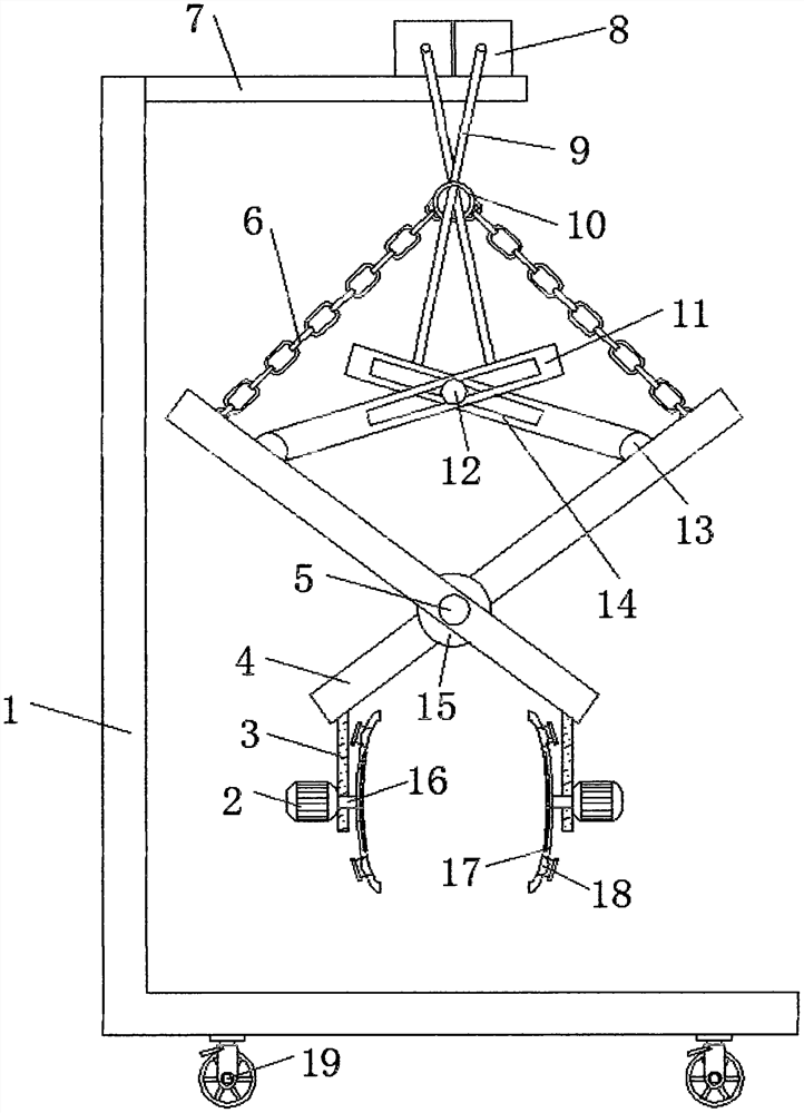
[0025] refer to Figure 1-2 , a clamping device for mechanical processing, including an L-shaped plate 1 and two steering handles 4, a top plate 7 is fixed by bolts on one side of the outer wall of the L-shaped plate 1 near the top, and the top outer wall of the top plate 7 is fixed by bolts There are two servo motors 8, and the same round rod 5 is inserted and rotated on one side of the outer wall of the two steering handles 4, and the outer wall of one side of the round rod 5 is fixed with a fixing seat 15 by bolts, and the two steering handles 4 are opposite to each other. A clamping mechanism is provided on one side of the outer wall near the bottom, and a hinge seat 13 is installed on the opposite side of the two steering handles 4 near the top, and the outer walls of the two hinge seats 13 are hinged with connecting rods 11. A rope 9 is wound around one end of the output shafts of the two servo motors 8 , and one end of the rope 9 is respectively bolted to one side outer...

Embodiment 2

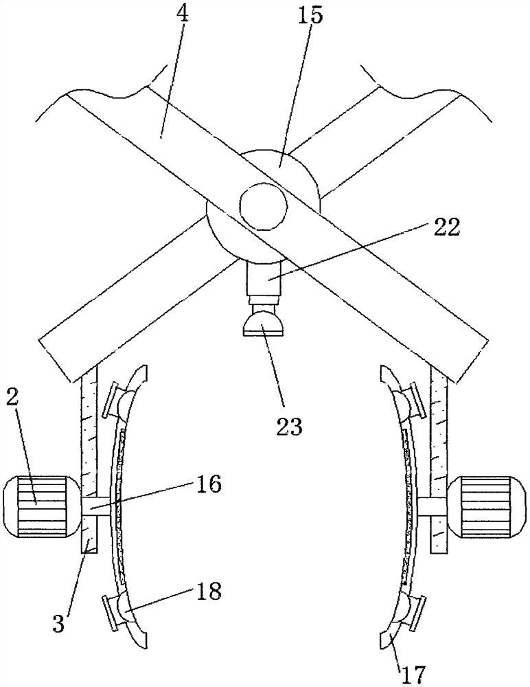
[0030] refer to image 3 , a clamping device for mechanical processing. Compared with Embodiment 1, the outer wall of the bottom of the fixed seat 15 is fixed with an electric telescopic rod 22 through a bolt, and one end of the extension rod of the electric telescopic rod 22 is fixed with a second bolt. Two electromagnetic chucks 23.

[0031] During use, the second electromagnetic chuck 23 can be used for auxiliary adsorption on the top of the clamping part when clamping, and the electric telescopic rod 22 is used to move the second electromagnetic chuck 23 to the surface of the clamping part, and then start the second electromagnetic chuck 23 carries out adsorption, and the fixing of auxiliary clip.


PUM


Abstract

The invention discloses a clamping device for mechanical processing. Aiming at the problem that it is inconvenient to clamp heavy objects and is easy to fall off, the following scheme is proposed, which includes an L-shaped plate and two steering handles. The outer wall of one side of the L-shaped plate is The position close to the top is fixed with a top plate by bolts, and two servo motors are fixed on the top outer wall of the top plate by bolts, and the same round rod is rotatably inserted on one side of the outer wall of the two steering handles, and one of the round rods A fixing seat is fixed on the side outer wall by bolts, and a clamping mechanism is provided at a position near the bottom of the opposite side outer wall of the two steering handles. The central hinge of the steering handle of the present invention is located near the bottom of the steering handle, so that the upper moment arm is larger than the lower moment arm, so that when the upper steering handle is folded, the lower arc splint bears a greater force, and when the arc splint starts to clamp After being held, the gravity of the clamped part makes the arc-shaped splint shrink more tightly, so that the arc-shaped splint is clamped tighter and will not loosen.

Description

technical field [0001] The invention relates to the technical field of clamping devices, in particular to a clamping device for machining. Background technique [0002] Machining refers to the process of changing the shape or performance of a workpiece through a mechanical device. According to the differences in processing methods, it can be divided into cutting processing and pressure processing. Sometimes arc-shaped workpieces are processed during machining, and clamping is required during processing, so it is necessary to use a clamping device for machining to clamp the parts to be processed. fixed. [0003] Existing clamping devices for mechanical processing on the market mostly have the following deficiencies: it is not convenient to clamp heavy objects, and it is easy to fall off when clamping, and existing patents are not easy to solve such problems. Therefore, there is an urgent need for a Machining uses a clamping device to solve the above problems. Contents of ...

Claims


Application Information

Patent Timeline
Patent Type & Authority Patents(China)
IPC IPC(8): B23Q7/04
CPCB23Q7/043
Inventor 洪永生梁学柱于亮军王双喜赵云
Owner 宁夏隆基宁光仪表股份有限公司
Why Eureka
Try Eureka