
Chain type dragging machine driven by oil cylinder

A chain-type, oil-cylinder technology, applied in the direction of fluid pressure actuating device, lifting device, hoisting device, etc., can solve the problems of limited length of the oil cylinder, large structure of the dragging mechanism, inconvenient assembly, etc., and achieve strong pulling power and convenient use. , the effect of simple structure

Pending Publication Date: 2020-10-02
大连宏远气动液压船舶辅机有限公司
View PDF0 Cites 0 Cited by
  • Summary
  • Abstract
  • Description
  • Claims
  • Application Information

AI Technical Summary

Problems solved by technology

[0002] The drag mechanism in the existing mechanical equipment mostly uses electric power as the power source of the entire drag mechanism, dragging the equipment to move in a straight line in the horizontal direction. This kind of drag mechanism has a large structure and is inconvenient to assemble, and is not suitable for ships or Underground and other special working places
In addition to electricity, there are also hydraulic cylinders used as the power source of the dragging mechanism. Since the hydraulic cylinder can perform reciprocating motion, the reciprocating motion of the hydraulic cylinder can be used to drag heavy objects or other functions related to the reciprocating motion of the oil cylinder. , but due to the limited length of the existing oil cylinders on the market, long-distance dragging motions cannot be realized, resulting in limited use of the dragging mechanism

Method used


Image

  • Chain type dragging machine driven by oil cylinder
  • Chain type dragging machine driven by oil cylinder
  • Chain type dragging machine driven by oil cylinder

Examples


Embodiment Construction

[0026] In order to make the structure and function of the present invention clearer, the technical solutions in the embodiments of the present invention will be clearly and completely described below in conjunction with the drawings in the embodiments of the present invention.

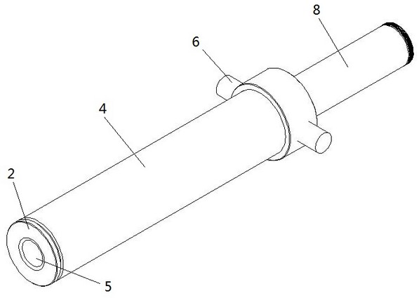
[0027] See attached Figure 1-5 , a cylinder-driven chain tractor, including a circular link chain 1 and a hydraulic cylinder; the hydraulic cylinder is equipped with a piston rod 8, and the center of the piston rod is set as a hollow cavity 22, and the piston rod 8 is connected to the inner wall of the cylinder barrel 4 of the hydraulic cylinder. Slidingly connected, the inside of the cylinder 4 has a central penetrating tube 5 for passing through the circular chain, the outer wall of the central penetrating tube 5 is slidingly connected with the inner wall of the hollow cavity 22 of the piston rod, and the end of the piston rod 8 The inner part is connected with an expansion lock head, and the ring c...


PUM


Abstract

The invention belongs to the technical field of dragging machines, and particularly relates to a horizontal chain type dragging machine driven by an oil cylinder. The machine comprises a chain and a telescopic mechanism, wherein a hollow cavity is formed in the center of a piston rod of the telescopic mechanism, the end of the piston rod is connected with a tensioning lock cylinder, the chain penetrates through the hollow cavity of the piston rod and the tensioning lock cylinder, and the tensioning lock cylinder locks or loosens the chain to enable the chain to move along with movement of thepiston rod. The chain type dragging machine is small in size, high in dragging force, capable of achieving long-distance dragging, simple in structure and convenient to use.

Description

technical field [0001] The invention belongs to the technical field of tractors, and in particular relates to a chain-type tractor driven by a horizontal oil cylinder. Background technique [0002] The drag mechanism in the existing mechanical equipment mostly uses electric power as the power source of the entire drag mechanism, dragging the equipment to move in a straight line in the horizontal direction. This kind of drag mechanism has a large structure and is inconvenient to assemble, and is not suitable for ships or Underground and other special working places. In addition to electricity, there are also hydraulic cylinders used as the power source of the dragging mechanism. Since the hydraulic cylinder can perform reciprocating motion, the reciprocating motion of the hydraulic cylinder can be used to drag heavy objects or other functions related to the reciprocating motion of the oil cylinder. , but due to the limited length of the existing oil cylinders on the market, ...

Claims


Application Information

Patent Timeline
Patent Type & Authority Applications(China)
IPC IPC(8): B66F19/00F15B15/14
CPCB66F19/00F15B15/14
Inventor 李金林张军张丽娟赵家国邓喜礼张鑫赵振宇陈超姜春雨
Owner 大连宏远气动液压船舶辅机有限公司
Learn More