Excavator hydraulic system anti-air-suction controlling method and controlling device and excavator

A technology of hydraulic system and control method, which is applied in earth mover/excavator, construction, etc. It can solve the problems of increased probability of problems, increased production costs, adjustment of speed and force deviation, etc., and achieves the goal of reducing the risk of air suction Effect

Pending Publication Date: 2020-10-02
WEICHAI POWER CO LTD +1
View PDF6 Cites 4 Cited by
  • Summary
  • Abstract
  • Description
  • Claims
  • Application Information

AI Technical Summary

Problems solved by technology

[0003] The existing methods to solve the problem of cavitation in the hydraulic system are mainly through the following two methods: (1) Increase the oil return back pressure scheme, also known as passive anti-cavitation. From a point of view, the smaller the oil return back pressure, the better, while increasing the oil return back pressure scheme will slow down the action speed; (2) The hydraulic oil regeneration scheme, which detects the pressure on the oil inlet side and the oil return side, according to the pressure difference Supplementing oil on the suction side can slow down the cavitation to a certain extent, but the regeneration of hydraulic oil is more focused on energy reuse. Tailor-made, there is a large deviation in the adjustment speed and strength
[0004] In addition, the above two methods can only adjust the anti-air suction of a single action of the excavator, and need to introduce new control valves, pipelines, etc., which increases the production cost and complicates the system, leading to problems. Increased chance

Method used


Image

  • Excavator hydraulic system anti-air-suction controlling method and controlling device and excavator
  • Excavator hydraulic system anti-air-suction controlling method and controlling device and excavator
  • Excavator hydraulic system anti-air-suction controlling method and controlling device and excavator

Examples


Embodiment Construction

[0042] The present invention will be further described in detail below in conjunction with the accompanying drawings and embodiments. It should be understood that the specific embodiments described here are only used to explain the present invention, but not to limit the present invention. In addition, it should be noted that, for the convenience of description, only some structures related to the present invention are shown in the drawings but not all structures.

[0043] It should be noted that the terms "first" and "second" in the specification, claims and drawings of the present invention are used to distinguish different objects, rather than to limit a specific order. The following embodiments of the present invention may be implemented independently, or may be implemented in combination with each other, which is not specifically limited in the embodiments of the present invention.

[0044] figure 1 It is a flow chart of an anti-cavitation control method for an excavato...


PUM


Abstract

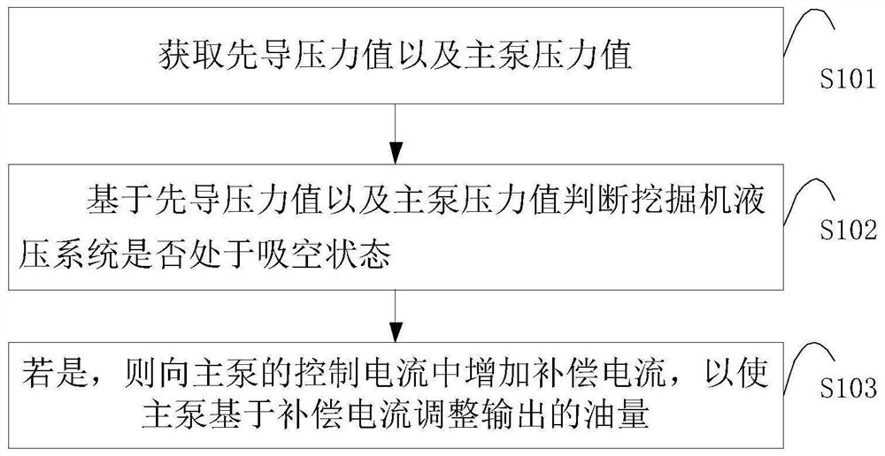
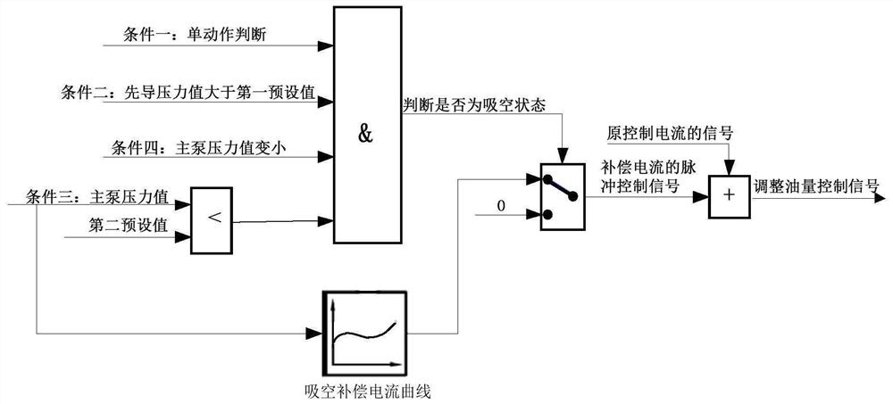
The invention discloses an excavator hydraulic system anti-air-suction controlling method and controlling device and an excavator. The controlling method comprises the steps that: a pilot pressure value and a main pump pressure value are acquired; whether an excavator hydraulic system is in an air sucking status is judged based on the pilot pressure value and the main pump pressure value; and if the excavator hydraulic system is in the air suck status, compensating current is added to controlling current of a main pump to enable the main pump to adjust output oil amount based on the compensating current. Electric signals replace traditional hydraulic signals in judging whether the hydraulic system is in an air sucking status; the air sucking risk is lowered in a manner that oil supply amount is actively added; and the technical effects that precise judgment on whether the hydraulic system is in an air sucking status can be realized without adding extra controlling components and that the air sucking risk is lowered via linear addition of the oil supply amount to the system.

Description

technical field [0001] The embodiments of the present invention relate to the technical field of excavators, in particular to an anti-cavitation control method, a control device and an excavator for a hydraulic system of an excavator. Background technique [0002] The positive flow hydraulic system has the advantages of low fuel consumption, high operating efficiency, and high reliability. It is widely used in hydraulic excavators. In case of valgus, stick retraction and valgus, etc., there will be air suction problems. [0003] The existing methods to solve the problem of cavitation in the hydraulic system are mainly through the following two methods: (1) Increase the oil return back pressure scheme, also known as passive anti-cavitation. From a point of view, the smaller the oil return back pressure, the better, while increasing the oil return back pressure scheme will slow down the action speed; (2) The hydraulic oil regeneration scheme, which detects the pressure on the...

Claims


Application Information

Patent Timeline
IPC IPC(8): E02F9/20E02F9/22
CPCE02F9/20E02F9/22E02F9/2221E02F9/2232E02F9/2235E02F9/2267
Inventor 张西田赵金光于鹏飞乔志刚
Owner WEICHAI POWER CO LTD
Why Eureka
Try Eureka