

Paving equipment for tunnel fireproof asphalt
An asphalt and tunnel technology, applied in the field of tunnel fireproof asphalt laying equipment, can solve the problems of reduced efficiency, danger to drivers, increased workload of staff, etc., and achieves the effects of convenient operation, high investment efficiency, and simple design structure
- Summary
- Abstract
- Description
- Claims
- Application Information
AI Technical Summary
Problems solved by technology
Method used
Image

Examples
Embodiment Construction
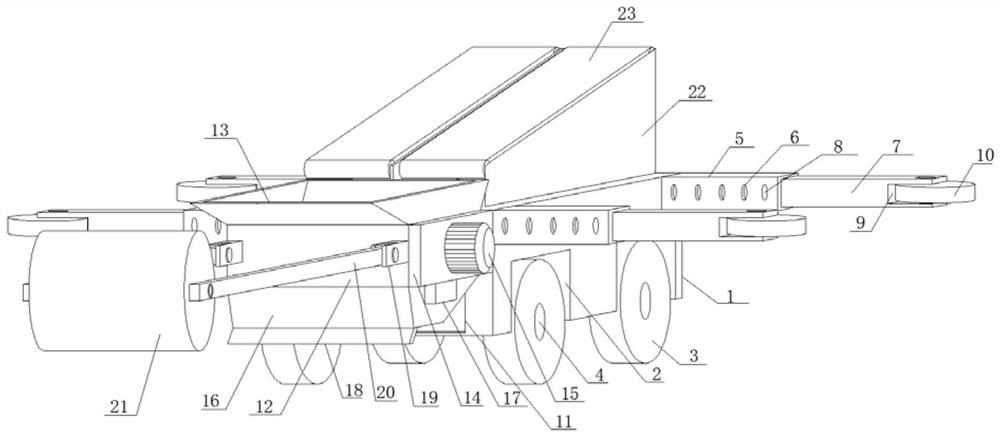
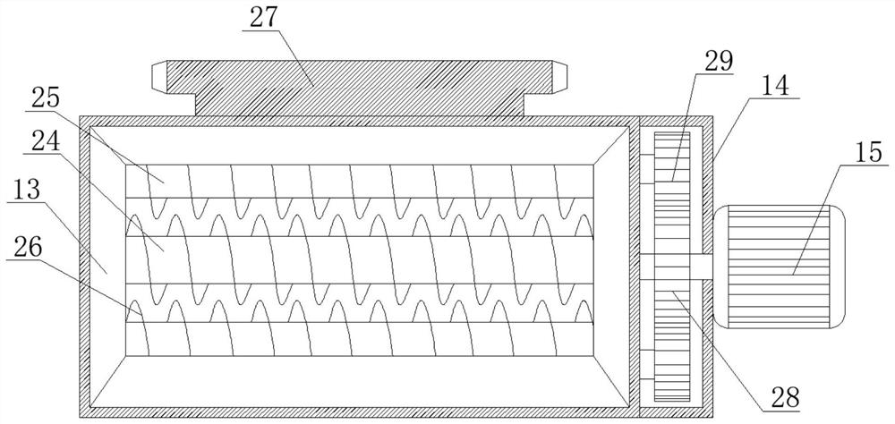
[0028] see Figure 1-2 , 8. In the embodiment of the present invention, a tunnel fireproof asphalt laying equipment includes a main support plate 1, and the two sides of the main support plate 1 are symmetrically provided with roller grooves 2, and the inner side of the roller groove 2 is provided with a driving wheel 3 , the central position of the driving wheel 3 is horizontally and fixedly plugged with a fixed shaft 4, the number of roller grooves 2 is four, and the four roller grooves 2 are arranged symmetrically in pairs on both sides of the main support plate 1 close to At both ends, the bottom of the roller groove 2 extends through the bottom surface of the main support plate 1 to the outer edge, and the outer edge of the driving wheel 3 extends through the bottom opening end of the roller groove 2 to the bottom surface of the main support plate 1, and drives The wheel 3 is fixedly plugged in the center of the inner side of the roller groove 2 through the fixed shaft 4....
PUM
 Abstract
Description
Claims
Application Information