
Device for melting down metal-containing material

a technology of metal-containing materials and devices, which is applied in the direction of lighting and heating apparatus, charge manipulation, furniture, etc., can solve the problems of not being able to efficiently process large amounts, and achieve the effects of reducing production costs, high investment and operational costs, and efficient processing large amounts

Inactive Publication Date: 2007-06-21
VOEST ALPINE AG
View PDF1 Cites 0 Cited by
  • Summary
  • Abstract
  • Description
  • Claims
  • Application Information

AI Technical Summary

Benefits of technology

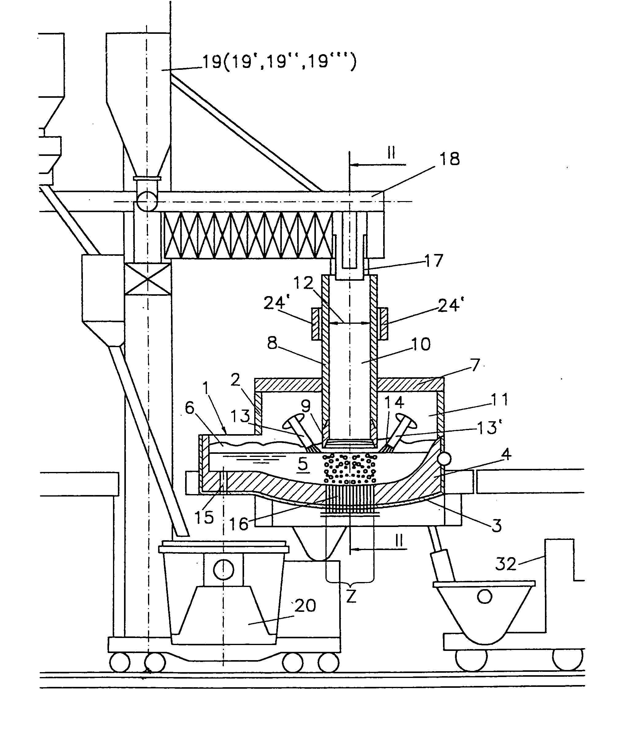
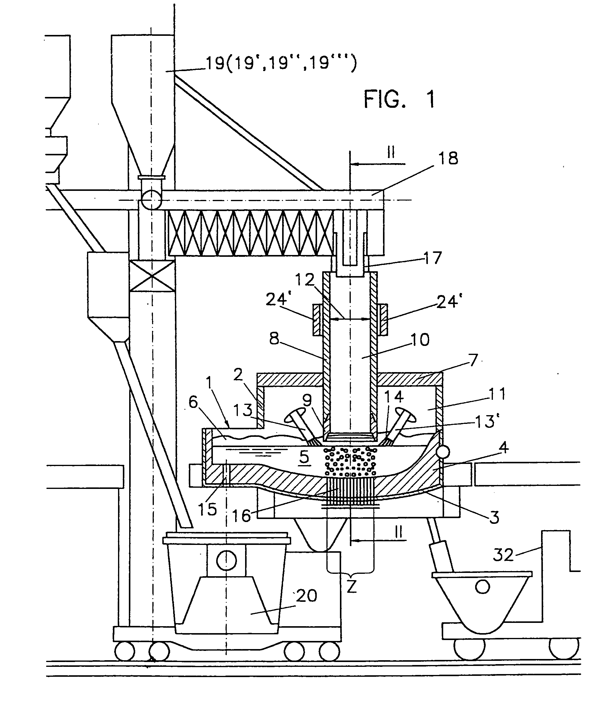
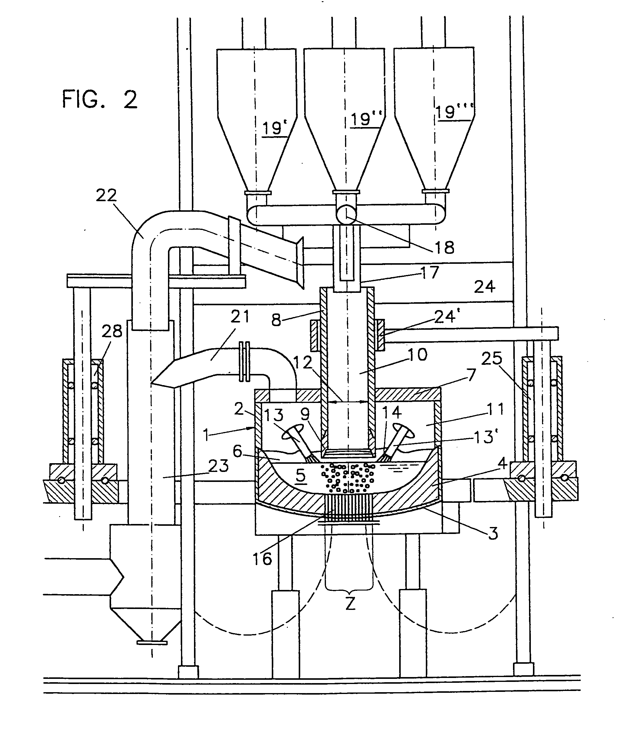
[0034] In order to attain a quick melting of the metal and within a short period of time a particularly thorough mixing of the metal-containing material with the slag at the outlet of the charging tube, it is advantageous to supply the energy necessary therefor in the immediate vicinity of the lower charging tube end.
[0035] Suitably, the metal-containing material is charged in lumpy and / or fine-particulate form. A particular advantage is derived from the method according to the invention if exclusively fine-particulate material is used. So far, it has not been feasible to efficiently process large amounts of, for instance, a million tons per year of fine-grained sponge iron to steel. The ore dust accruing in large amounts, which is available on the raw material market at very favourable prices, therefore, had to be rendered usable for the direct reduction in pelletizing plants of high investment and operational costs for the production of ore pellets or the produced fine-particulate sponge iron had to be processed to sponge iron briquettes in hot briquetting plants after the direct reduction. However, the invention offers the possibility of substantially lowering the production costs for the liquid metal, and that solely by the use of ore dust.

Problems solved by technology

So far, it has not been feasible to efficiently process large amounts of, for instance, a million tons per year of fine-grained sponge iron to steel.

Method used


Image

  • Device for melting down metal-containing material
  • Device for melting down metal-containing material
  • Device for melting down metal-containing material

Examples


Embodiment Construction

[0041] According to a preferred embodiment of the method of the invention, the metal-containing material is charged into the melting furnace through the charging tube in the hot and / or cold state, preferably at a temperature of between 500° C. and 1000° C., most preferably of between 600° C. and 700° C., which roughly corresponds to the temperature sponge iron has after being directly reduced. In that manner, energy costs can be saved, if, prior to being melted down, the charging material was subjected to a process which led to an increase in temperature of the particles, since the energy immanent to the charged material may be used for lowering the necessary melting energy consumption without any particular plant-related technical expenditures. That is rendered feasible by the particularly simple charging according to the invention, which does not necessitate any mechanical elements in the high temperature region of the melting furnace.

[0042] A preferred application of the method ...


PUM

PropertyMeasurementUnit
diameteraaaaaaaaaa
diameteraaaaaaaaaa
angleaaaaaaaaaa

Abstract

In a method and a device for melting down metal-containing material, preferably fine-particulate metal-containing material, such as sponge iron, in a metallurgical melting furnace (1), wherein, in an interior space (11) of the melting furnace (1), a metal melt (5) and a slag layer (6) floating on top of the metal melt (5) are maintained, the metal-containing material is added by means of a supply means dipping into the slag layer (6) and energy is added in the form of electric arcs (14), the metal-containing material is charged directly into the central region (Z) of the melting furnace (1) by means of at least one charging tube (8) exclusively serving for conveying material via the charging tube outlet (9) of the same, the electric arcs (14) are directed obliquely towards the metal melt (5) against the central region (Z) of the melting furnace (1) and the metal-containing material is melted in the slag layer (6) and a mixed process slag-metal melt is maintained in the region of the charging tube outlet (9). (FIG. 1).

Description

[0001] This application is a division of U.S. Ser. No.: 10 / 021,373, filed Oct. 22, 2001 which is a continuation of PCT / AT00 / 00101, filed Apr. 20, 2000, both which are incorporated by reference herein. PCT / AT00 / 00101 was published in German under Publication No.: WO / 00 / 65102.[0002] The invention relates to a method and a device for melting down metal-containing material, preferably fine-particulate metal-containing material, such as sponge iron, in a metallurgical melting furnace, wherein, in an interior space of the melting furnace, a metal melt and a slag layer floating on top of the metal melt are maintained and the metal-containing material is added by means of a supply means dipping into the slag layer and energy is added in the form of electric arcs. BACKGROUND OF INVENTION [0003] A big unsolved problem is the processing of large amounts of fine-particulate metal-containing material, for example of one million tons per year. Until today, the charging, most often blowing, of fin...

Claims


Application Information

Patent Timeline
Patent Type & Authority Applications(United States)
IPC IPC(8): C21C5/52C21B13/12C21B13/14C21C5/56F27B3/06F27B3/10F27B3/18F27D3/12F27D17/00
CPCC21B13/12C21B13/14C21C5/527C21C5/565F27B3/065F27B3/10F27B3/183F27D17/003F27D2003/127Y02P10/20
Inventor BERGER, HARALDMITTAG, PETERAIGNER, BERNHARD
Owner VOEST ALPINE AG
Learn More