Laser smelting furnace with water cooled copper mould and method for smelting ingot
A technology of water-cooled copper mold and laser smelting, which is applied in the field of smelting furnaces for smelting alloys, can solve problems such as complex smelting processes, and achieve the effects of short smelting time, high purity of alloys, and accurate chemical components of alloys
- Summary
- Abstract
- Description
- Claims
- Application Information
AI Technical Summary
Problems solved by technology
Method used
Image
Examples
Embodiment 1
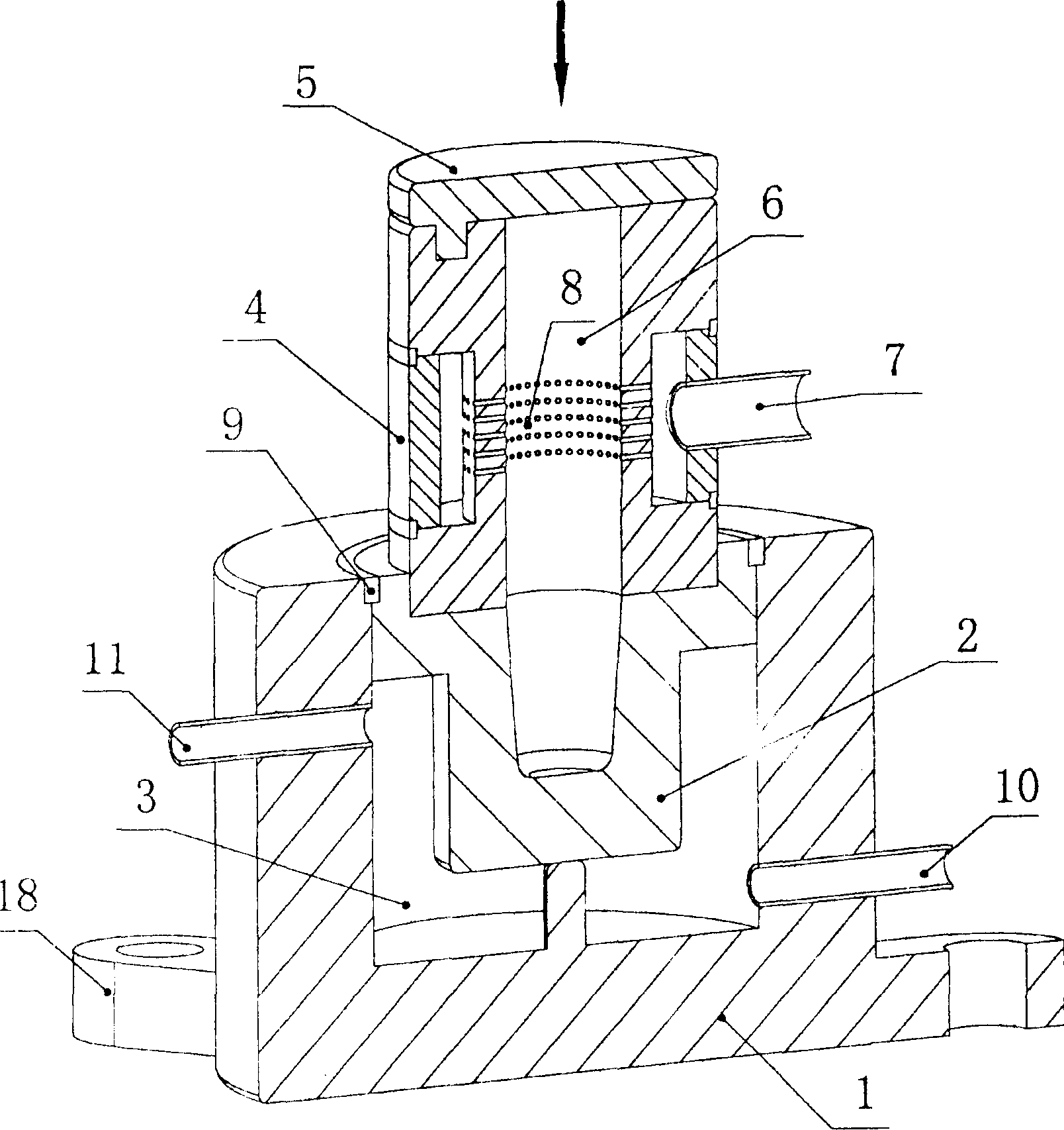
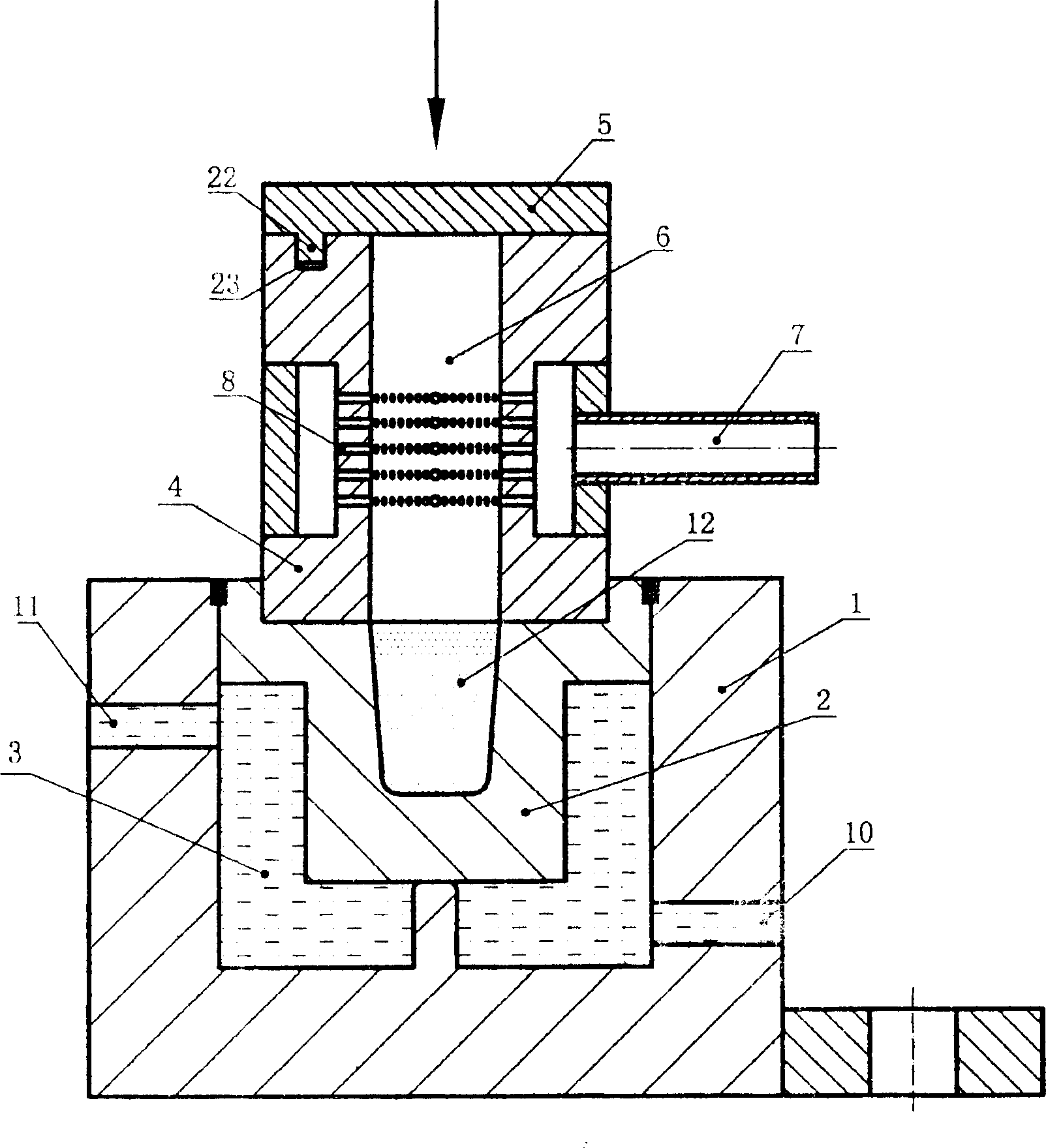
[0041] The water-cooled copper mold laser smelting furnace of the present invention comprises a furnace body 1, a copper mold 2, a cooling water device, an atmosphere protection device, an upper furnace body 4, an upper cover 5, the bottom of the upper cover 5 is provided with a pin 22, the pin 22 is inserted into the pin hole 23 of the upper furnace body 4; the upper furnace body 4 is provided with a pin hole 23 on one end surface, and the other end is sealed and installed together with the furnace body 1 using a seal 9, and the air inlet pipe 7 of the atmosphere protection device is located on the upper On the furnace body 4, the protective gas outlet 8 is arranged on the inner wall around the atmosphere protection chamber 6 through which the protective gas passes; between the furnace body 1 and the copper mold 2 is a cooling water circulation chamber 3, and the cooling water circulation chamber 3 is provided with a water inlet 10 and a water outlet 11; with the furnace body ...
Embodiment 2
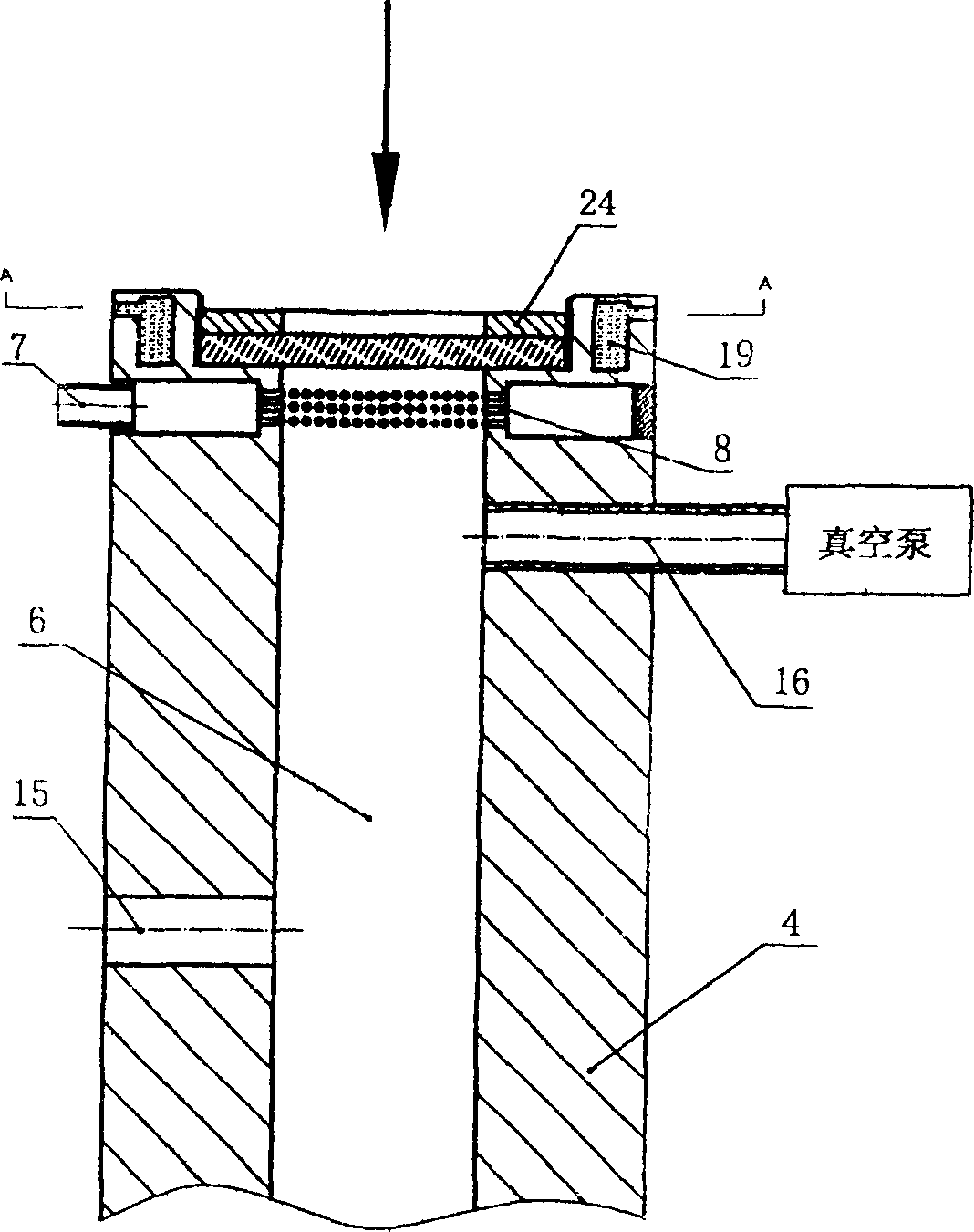
[0055]The water-cooled copper mold laser melting furnace of the present invention comprises a furnace body 1, a copper mold 2, a cooling water device, an atmosphere protection device, an upper furnace body 4, a laser window fastener 24, a laser window cooling water circulation cavity 19, an upper furnace body 4. The sealing member 9 is sealed and installed together with the furnace body 1. The air intake pipe 7 of the atmosphere protection device is arranged on the upper furnace body 4, and the protective gas outlet 8 is arranged on the inner wall around the atmosphere protection chamber 6 through which the protective gas passes; Between the furnace body 1 and the copper mold 2 is a cooling water circulation chamber 3, the cooling water circulation chamber 3 is provided with a water inlet 10 and a water outlet 11; there are fasteners 18 integrated with the furnace body 1, and the fasteners 18 are used To fix the body of furnace 1; what the heat source of melting alloy adopts is...
Embodiment 3
[0071] The water-cooled copper mold laser melting furnace of the present invention comprises a furnace body 1, a copper mold 2, a cooling device, an atmosphere protection device, and an upper furnace body 4. The upper furnace body 4 is sealed and installed together with the furnace body 1 using a seal 9; the air inlet pipe 7 of the atmosphere protection device is arranged on the upper furnace body 4, and the protective gas outlet 8 is arranged around the atmosphere protection chamber 6 through which the protective gas passes. On the inner wall, a plurality of alloy powder input ports 14 are provided on the top of the upper furnace body 4; between the furnace body 1 and the copper mold 2 is a cooling water circulation chamber 3, and the cooling water circulation chamber 3 is provided with a water inlet 10 and a water outlet 11 There are also fasteners 18 integrated with the body of furnace 1, and the fasteners 18 are used to fix the body of furnace 1; the heat source for smeltin...
PUM
 Abstract
Description
Claims
Application Information
 - R&D
- Intellectual Property
- Life Sciences
- Materials
- Tech Scout
- Unparalleled Data Quality
- Higher Quality Content
- 60% Fewer Hallucinations
Browse by: Latest US Patents, China's latest patents, Technical Efficacy Thesaurus, Application Domain, Technology Topic, Popular Technical Reports.
© 2025 PatSnap. All rights reserved.Legal|Privacy policy|Modern Slavery Act Transparency Statement|Sitemap|About US| Contact US: help@patsnap.com


