Liquid spraying screw rod compressor system

A screw compressor and compressor technology, applied in the field of compressors, can solve the problems of high current of the air compressor motor, dead contacts burning, blockage of the oil separation core, etc., to achieve the effect of improving precise separation, avoiding deviation, and cleaning friction

Inactive Publication Date: 2020-10-02
曹永民
View PDF0 Cites 0 Cited by
  • Summary
  • Abstract
  • Description
  • Claims
  • Application Information

AI Technical Summary

Problems solved by technology

[0002] Liquid injection screw compressors are mainly used in higher pressure ratio processes, giving full play to the advantages of the equipment. Most of the process gas screw compressors are operated by liquid injection. On the one hand, it can control the temperature rise in the compression process and prevent the unit from being damaged. On the other hand, it can improve the gap sealing effect and increase the volumetric efficiency. During the operation of the compression molding machine, it is also necessary to reduce the oil content in the exhaust of the unit and recycle the lubricating oil in the unit. If the lubricating oil cannot be separated well , the lubricating oil will be discharged along with the compressed air, resulting in high oil consumption. This phenomenon is also called oil leakage. The main reason for this is that the oil separation core is blocked or the excessive pressure deforms the oil separation core, resulting in air compressor If the motor current is too large, if the motor is overloaded seriously, the host will be locked, and if it is serious, the contacts will burn and cause a major accident

Method used


Image

  • Liquid spraying screw rod compressor system
  • Liquid spraying screw rod compressor system
  • Liquid spraying screw rod compressor system

Examples


Embodiment 1

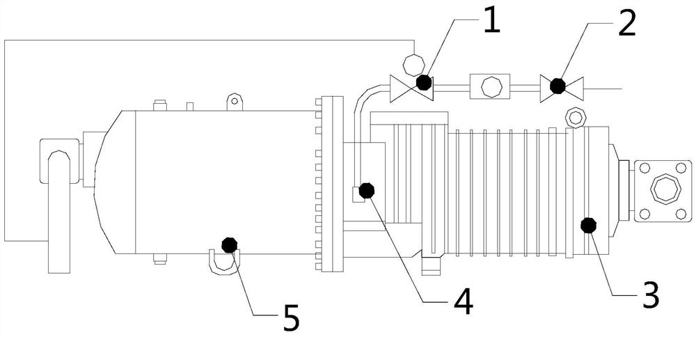
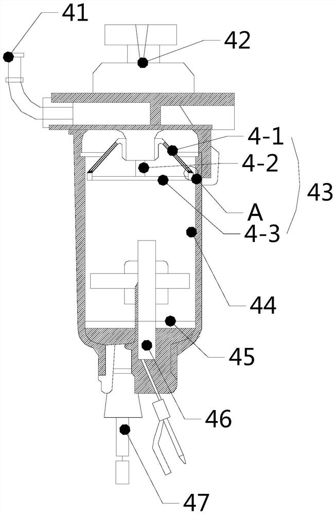
[0024] see Figure 1-Figure 4 , a liquid spraying screw compressor system, the present invention provides a liquid spraying screw compressor system, its structure includes a first valve 1, a second valve 2, a screw 3, an oil separator 4, a compressor 5, the compression The machine 5 is mechanically connected to the screw 3 through a shaft, and an oil separator 4 is installed at the position where the screw 3 is mechanically connected to the compressor 5, and the oil separator 4 is mechanically connected through the first valve 1, the second valve 2 and the condenser. connection, the first valve 1 is mechanically connected to the compressor 5 through pipelines, and the oil separator 4 includes an oil outlet 41, a manual diaphragm pump 42, an oil inlet, an oil separator core 43, a valve body 44, and a float 45 , a liquid level sensor 46, a drain plug 47, the top of the valve body 44 is equipped with a hand-pressed diaphragm pump 42, and the horizontal ends of the valve body 44 b...

Embodiment 2

[0032] see Figure 1-Figure 4 , a liquid spraying screw compressor system, the present invention provides a liquid spraying screw compressor system, its structure includes a first valve 1, a second valve 2, a screw 3, an oil separator 4, a compressor 5, the compression The machine 5 is mechanically connected to the screw 3 through a shaft, and an oil separator 4 is installed at the position where the screw 3 is mechanically connected to the compressor 5, and the oil separator 4 is mechanically connected through the first valve 1, the second valve 2 and the condenser. connection, the first valve 1 is mechanically connected to the compressor 5 through pipelines, and the oil separator 4 includes an oil outlet 41, a manual diaphragm pump 42, an oil inlet, an oil separator core 43, a valve body 44, and a float 45 , a liquid level sensor 46, a drain plug 47, the top of the valve body 44 is equipped with a hand-pressed diaphragm pump 42, and the horizontal ends of the valve body 44 b...


PUM


Abstract

The invention discloses a liquid spraying screw rod compressor system, and the system structurally comprises a first valve, a second valve, a screw rod, an oil separator and a compressor, wherein thecompressor is in mechanical connection with the screw rod through a rotating shaft device, the oil separator is mounted at a position of the mechanical connection between the screw rod and the compressor, and the oil separator is in mechanical connection with the first valve, the second valve and a condenser. In the system provided by the invention, by design of a netted core in the shape of a round table, and design of different size, under a condition where an oil separation core generates deformation, a cavity of a valve body cannot be blocked; and by design of three layers of filter screens including a first filter screen, a second filter screen and a third filter screen, accurate separation in the system is improved further, an effect of gas-oil separation is guaranteed to be better,meanwhile, a flat bar design in the first filter screen, the second filter screen and the third filter screen is used as a support, thus, support force of the first filter screen, the second filter screen and the third filter screen is improved, and the first filter screen, the second filter screen and the third filter screen are guaranteed to be free from generating serious deformation.

Description

technical field [0001] The invention relates to the field of compressors, in particular to a liquid spray screw compressor system. Background technique [0002] Liquid injection screw compressors are mainly used in higher pressure ratio processes, giving full play to the advantages of the equipment. Most of the process gas screw compressors are operated by liquid injection. On the one hand, it can control the temperature rise in the compression process and prevent the unit from being damaged. On the other hand, it can improve the gap sealing effect and increase the volumetric efficiency. During the operation of the compression molding machine, it is also necessary to reduce the oil content in the exhaust of the unit and recycle the lubricating oil in the unit. If the lubricating oil cannot be separated well , the lubricating oil will be discharged along with the compressed air, resulting in high oil consumption. This phenomenon is also called oil leakage. The main reason for...

Claims


Application Information

Patent Timeline
Patent Type & Authority Applications(China)
IPC IPC(8): F04C29/02B01D46/12
CPCB01D46/12F04C29/026
Inventor 曹永民
Owner 曹永民
Why Eureka
Try Eureka