A Highway Tunnel Light Environment System for Improving Driver's Visual Distance

A road tunnel, visual distance technology, applied in the direction of roads, light sources, roads, etc., can solve the problems of not considering the visual comfort of lighting brightness, affecting the visual distance of human eyes, visual fatigue, etc., to increase the sense of hierarchy and safety boundary effect, Eliminates darkness, depression and glare, and reduces psychological stress

Active Publication Date: 2022-06-07
ANHUI ZHONGYI NEW MATERIAL TECH CO LTD
View PDF5 Cites 0 Cited by
  • Summary
  • Abstract
  • Description
  • Claims
  • Application Information

AI Technical Summary

Problems solved by technology

At present, although the tunnel lighting technical specification divides the lighting of the tunnel into the entrance and exit lighting section, the transition section lighting section and the basic section lighting section, different lighting sections also set different lighting brightness parameters, but it does not consider the lighting brightness, color temperature and people. At the same time, because the human eye’s photosensitive cone cells are sensitive to a spectral wavelength of 555nm and rod cells are sensitive to a spectral wavelength of 507nm, while the current light source spectrum of artificial lamps is between 480nm and 580nm (see figure 2 ) and are often discontinuous, which affects the visual distance of the human eye. Under the same road surface brightness uniformity, even if the illumination brightness of the natural light source is smaller than that of various lamp light sources, the human eye visual distance is still far away under the natural light source. For the latter; the dark and dull phenomenon of the inner wall and vault of the tunnel will cause psychological fear and pressure to the driver, and cause visual fatigue

Method used


Image

  • A Highway Tunnel Light Environment System for Improving Driver's Visual Distance
  • A Highway Tunnel Light Environment System for Improving Driver's Visual Distance
  • A Highway Tunnel Light Environment System for Improving Driver's Visual Distance

Examples


Embodiment Construction

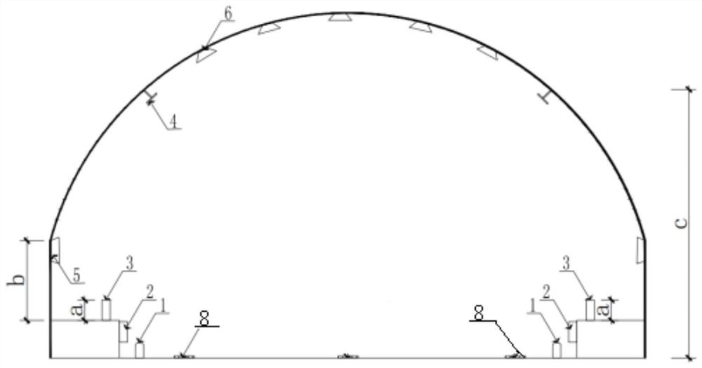
[0016] like image 3 As shown, a road tunnel light environment device that can improve the driver's visual distance,

[0017] Protruding road marking lights 1 are set on both sides outside the road marking line 8 of the highway tunnel, and the top surface of the protruding road marking lights is 2 to 2.5 cm higher than the road surface; contour lights 2 are set at half the height of the maintenance road wall on both sides of the highway tunnel. The direction lights 3 with a height a of 10-30cm are set on the top surface of the maintenance road on both sides of the highway tunnel, and the wall lighting fixtures 4 are set on the wall surfaces on both sides of the tunnel at a height of 3-5m from the road surface. Above the maintenance road on both sides of the tunnel The wall profile marks 5 with a distance of 8 to 32m are set on the position b of the arch wall wall at a height of 50 to 70cm, and the vault is set on the tunnel vault at a longitudinal distance of 4 to 40m along th...


PUM


Abstract

The invention discloses a road tunnel light environment system for improving the driver's visual distance. Protruding road sign lights are arranged on both sides outside the road surface marking line of the road tunnel, contour lights are arranged at half the height of the wall surface of the inspection road, and the top surface of the inspection road Set direction lights, set wall lighting fixtures on the wall of the tunnel, set wall contour marks on the arch wall above the inspection road, and set vault guidance marks on the tunnel vault; the contour lights and direction lights are composed of light source LEDs and retroreflective materials. The wall delineation mark and the vault guide mark are made of retroreflective materials and polymer plastic or aluminum. The lighting of the entrance and exit sections of the tunnel and the transition section can be controlled in real time during the day, and the wall lighting fixtures are turned off at night. The wall lighting fixtures of the basic section of the tunnel Turn on day and night. Through the reflection of the tunnel wall and vault, the contrast between the color and the brightness of the wall, vault and road surface can be used to eliminate visual fatigue and reduce the safety accident rate.

Description

technical field [0001] The invention relates to the field of safe operation of highway tunnels, in particular to a highway tunnel light environment system for improving the visual distance of drivers. Background technique [0002] In the operation of highway tunnels, uninterrupted lighting is required in the tunnel, which consumes a lot of electricity and has a high safety accident rate. At present, the technical specifications of highway tunnels stipulate the brightness of road lighting and the uniformity of road lighting, but the test shows that the light environment quality of road tunnels not only includes the brightness and uniformity of road lighting, but also includes the relationship between the color temperature of the lighting source and the brightness of the lighting, the spectral wavelength of the light source and the tunnel lighting. The contrast between the vault and the wall surface and the brightness of the road surface, in the tunnel lighting environment, as...

Claims


Application Information

Patent Timeline
Patent Type & Authority Patents(China)
IPC IPC(8): F21S10/00F21V7/24F21V19/00F21V23/00E01F9/50E01F9/547E01F9/559F21Y115/10F21W131/101
CPCF21S10/00F21V7/24F21V19/001F21V23/003E01F9/50E01F9/547E01F9/559F21Y2115/10F21W2131/101Y02B20/40
Inventor 冯守中王军李洁高巍冒卫星屈双双
Owner ANHUI ZHONGYI NEW MATERIAL TECH CO LTD
Why Eureka
Try Eureka