Laser direct imaging optical system

A laser direct imaging and optical system technology, applied in the field of laser direct imaging, can solve problems such as energy variation, uneven energy distribution, waste of cost, etc., and achieve the effect of improving stability and product yield

Inactive Publication Date: 2020-10-02
TZTEK TECH
View PDF3 Cites 4 Cited by
  • Summary
  • Abstract
  • Description
  • Claims
  • Application Information

AI Technical Summary

Problems solved by technology

[0002] During the use of the laser direct imaging optical system, the laser inevitably has the problem of energy change (energy attenuation and energy distribution). During the phot

Method used


Image

  • Laser direct imaging optical system

Examples


Embodiment Construction

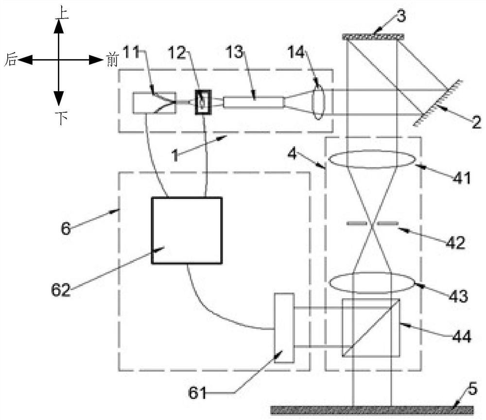
[0037] In order to make the purpose, technical solutions and advantages of the embodiments of the present invention more clear, the following will clearly and completely describe the technical solutions of the embodiments of the present invention in conjunction with the drawings of the embodiments of the present invention. Apparently, the described embodiments are some, not all, embodiments of the present invention. All other embodiments obtained by those skilled in the art based on the described embodiments of the present invention belong to the protection scope of the present invention.

[0038] Unless otherwise defined, the technical terms or scientific terms used in the present invention shall have the usual meanings understood by those skilled in the art to which the present invention belongs. "First", "second" and similar words used in the present invention do not indicate any order, quantity or importance, but are only used to distinguish different components. Likewise...


PUM


Abstract

The invention provides a laser direct imaging optical system, which comprises: laser light source lighting equipment; digital micro-mirror device equipment arranged above the laser light source lighting equipment; a photoetching imaging lens arranged below the digital micro-mirror device equipment, wherein the photoetching imaging lens comprises a beam splitter prism, and the beam splitter prism can split laser into P laser and S laser; and laser energy tracking equioment, wherein the laser energy tracking equipment is arranged to face the photoetching imaging lens, receives the S laser, tracks the energy of the S laser and generates an adjusting signal based on the tracked energy of the S laser, and the laser light source lighting equipment performs adjustment based on the adjusting signal. According to the laser direct imaging optical system, the energy change of the laser can be automatically tracked and adjusted in time, and the stability of the laser energy is improved.

Description

technical field [0001] The invention relates to the field of laser direct imaging, in particular to a laser direct imaging optical system. Background technique [0002] During the use of the laser direct imaging optical system, the laser inevitably has the problem of energy change (energy attenuation and energy distribution). During the photolithography process of the optical system, the product (including photoresist) is very sensitive to energy fluctuations. , It is easy to lead to product scrapping and waste of cost. Contents of the invention [0003] In view of this, the present invention provides a laser direct imaging optical system, which can automatically and accurately track the energy change of the laser in time, and adjust it in time to improve the stability of the laser energy and improve the product yield. [0004] In order to solve the above technical problems, the present invention provides a laser, including: [0005] Laser light source lighting equipment...

Claims


Application Information

Patent Timeline
IPC IPC(8): G03F7/20G02B27/28G02B27/09
CPCG03F7/2053G03F7/2057G02B27/286G02B27/0927G02B27/0938G03F7/70075G03F7/70191G03F7/70241G03F7/70291
Inventor 祝锁刘长清陶帅洋曹葵康温延培
Owner TZTEK TECH
Why Eureka
Try Eureka