
Energy-saving pot

An energy-saving pot and pot body technology, which is applied to the structure of cooking utensils, heating devices, cooking utensils, etc., can solve the problems of low heat utilization rate at the bottom of the pot, and the bottom of the pot is not in the heat conduction state, so as to achieve high heating efficiency and improve Heating efficiency and the effect of increasing the heating area

Pending Publication Date: 2020-10-09
程中贵
View PDF0 Cites 0 Cited by
  • Summary
  • Abstract
  • Description
  • Claims
  • Application Information

AI Technical Summary

Problems solved by technology

[0003] The existing cooktops generally use two types of pans and concave pots. The bottom of the pot body is smooth. When the flame is sprayed upward or burns directly to the bottom of the pot, the hot air flow immediately spreads to the surrounding 360 degrees, so the heat flow changes direction. The highest flame temperature is the outer flame of the open flame, but at this time the outer flame is not in the best heat conduction state with the bottom of the pot, so this is also a major reason for the low heat utilization rate of the bottom of the pot

Method used


Image

  • Energy-saving pot
  • Energy-saving pot
  • Energy-saving pot

Examples


Embodiment Construction

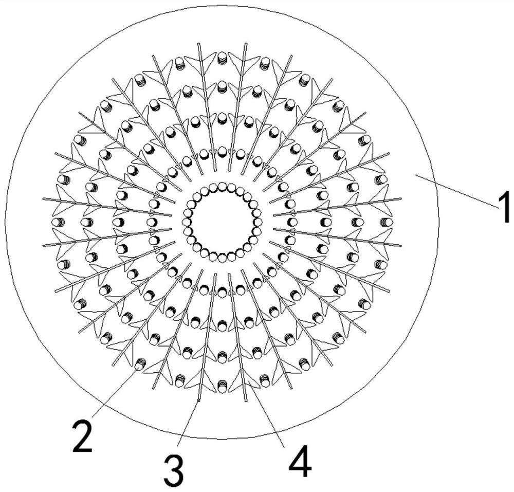
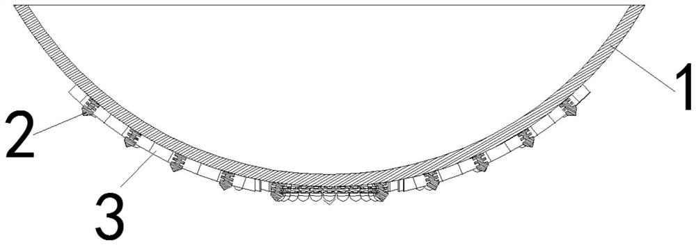
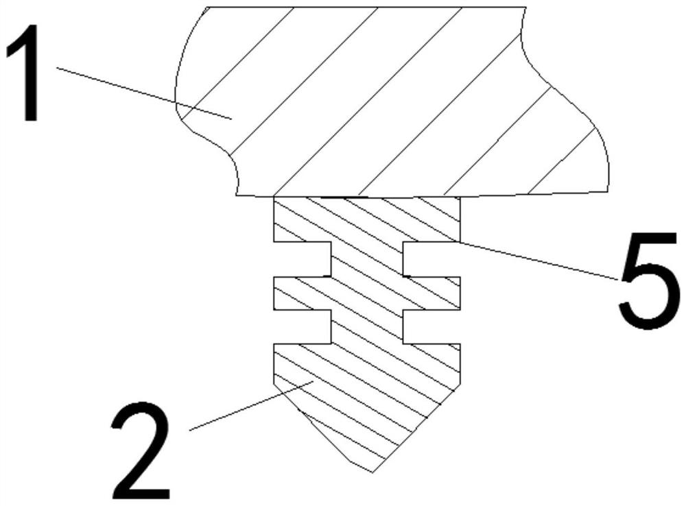
[0023] The following will be combined with Figure 1-3 , clearly and completely describe the technical solutions of the present invention, and obviously, the described embodiments are part of the embodiments of the present invention, but not all of them. Based on the embodiments of the present invention, all other embodiments obtained by persons of ordinary skill in the art without making creative efforts belong to the protection scope of the present invention.

[0024] In the description of the present invention, it should be understood that the orientation or positional relationship indicated by the terms "upper", "lower", "front", "rear", "inner", "outer" etc. Orientation or positional relationship is only for the convenience of describing the present invention and simplifying the description, and does not indicate or imply that the referred device or element must have a specific orientation, be constructed and operated in a specific orientation, and thus should not be cons...


PUM


Abstract

The invention discloses an energy-saving pot. The pot comprises a pot body, nail groups, guide plates and a drainage block, the bottom of the pot body is fixedly connected with the multiple nail groups and the multiple guide plates, the nail group comprises a plurality of fired nails, the nail groups are distributed in a circumferential array mode around the center of the bottom of the outer sideof the pot body, a plurality of the fired nails in the nail group and the center of the bottom of the outer side of the pot body form a radial structure, the innermost fired nails in the nail groups form a closed circular structure in a surrounding manner, the plurality of guide plates are distributed in a circumferential array around the center of the bottom of the outer side of the pot body, thenail group is arranged between the two guide plates, drainage blocks are arranged on the two sides of the fired nail between every two adjacent guide plates, the guide blocks on the two sides of thefired nail are of a symmetrical structure and fixedly connected with the two adjacent guide plates respectively, each guide block is of an arc-shaped structure, the arc-shaped structures are used forguiding heat and flames to the fired nail, an annular groove is formed in the side face of the fired nail, and the technical problems that in the prior art, the heat utilization rate of the pot bottomis not high are solved.

Description

technical field [0001] The invention relates to the field of energy-saving pots, in particular to an energy-saving pot. Background technique [0002] The energy-saving technical transformation of the cooktop usually includes: the heat preservation and heat insulation of the cooker chamber, the contrast between gas and air, the premixing effect, the combustion form of the flame according to the different cooker bodies, and the discharge of exhaust gas after combustion, etc. [0003] The existing cooktops generally use two types of pans and concave pots. The bottom of the pot body is smooth. When the flame is sprayed upward or burns directly to the bottom of the pot, the hot air flow immediately spreads to the surrounding 360 degrees, so the heat flow changes direction. The highest flame temperature is the outer flame of the open flame, but at this time the outer flame and the bottom of the pot are not in the best heat conduction state, so this is also a major reason for the l...

Claims


Application Information

Patent Timeline
Patent Type & Authority Applications(China)
IPC IPC(8): A47J27/00A47J36/00A47J36/24
CPCA47J27/002A47J36/00A47J36/24
Inventor 程中贵
Owner 程中贵
Learn More