Steel ball grinding scrap removing and screening device based on bearing internal assembly

A screening device and component technology, which is applied in grinding/polishing safety devices, sieves, solid separation, etc., can solve the problems of low working efficiency of the device and inability to completely remove waste debris, etc., and achieve convenient operation and improved The effect of screening efficiency

Inactive Publication Date: 2020-10-09
烟台德聚仁和智能科技有限公司
View PDF0 Cites 0 Cited by
  • Summary
  • Abstract
  • Description
  • Claims
  • Application Information

AI Technical Summary

Problems solved by technology

[0003] At present, after the steel balls of the internal components of the bearing are polished, impurities such as abrasives and waste chips on the surface of the steel balls need to be removed. The debris on the surface of the ball makes the working efficiency of the device lower. Therefore, it is urgent to design a kind of debris removal and screening device for grinding steel balls based on the internal components of the bearing to solve the above problems

Method used


Image

  • Steel ball grinding scrap removing and screening device based on bearing internal assembly
  • Steel ball grinding scrap removing and screening device based on bearing internal assembly
  • Steel ball grinding scrap removing and screening device based on bearing internal assembly

Examples


Embodiment 1

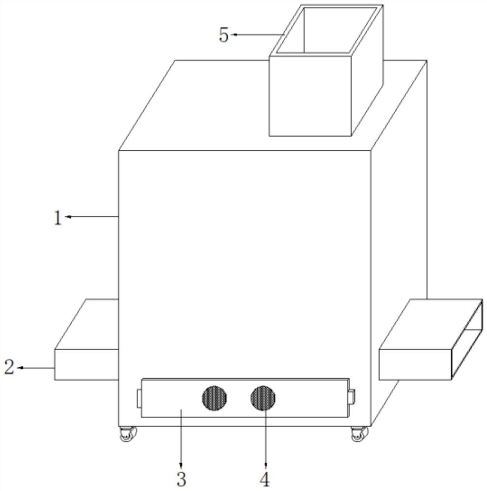
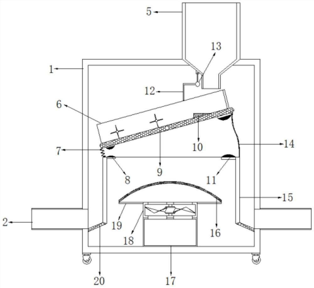
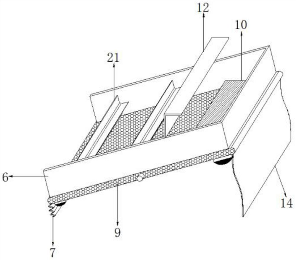
[0032] refer to Figure 1-5 , a steel ball grinding waste screening device based on the internal components of the bearing, including a treatment box 1, the top side of the treatment box 1 is connected with a feed hopper 5 by bolts, and the inner walls of the two sides of the treatment box 1 are close to the top The first screen cloth 9 is connected with the first screen cloth 9 by pin rotation between the middle position, and the two ends of the both sides inner walls near the bottom of the processing box 1 are welded with a baffle plate 15, and the top of one of the baffle plate 15 is connected with the first screen cloth 9 The first cloth bag 7 is fixedly connected between the bottom one end of the bottom, and the second cloth bag 14 is fixedly connected between the top of the other baffle plate 15 and the bottom other end of the first screen cloth 9, and one side top of one baffle plate 15 and One side of the bottom of the first screen 9 is welded with a first mount, and t...

Embodiment 2

[0041] refer to Figure 6-7 , a steel ball grinding based on the internal components of the bearing and a waste-removing screening device. Compared with Embodiment 1, the top of the first screen 9 is welded with blanking plates 24 distributed equidistantly, and the blanking The plate 24 is arranged in an S-shape.

[0042] Working principle: Since the blanking plate 24 is set in an S shape, when the steel balls and waste chips slide up and down the first screen 9, the S-shaped blanking plate 24 is used to increase the sliding distance of the steel balls, so that the waste chips can be fully through the first sieve 9.


PUM


Abstract

The invention discloses a steel ball grinding scrap removing and screening device based on a bearing internal assembly. The steel ball grinding scrap removing and screening device comprises a treatment box. One side of the top of the treatment box is fixedly connected with a feed hopper. A first screen net is arranged between the middle positions, close to the top, of the inner walls of the two sides of the treatment box. Baffles are fixedly connected between the two ends, close to the bottom, of the inner walls of the two sides of the treatment box. A first cloth bag is fixedly connected between the top of one baffle and one end of the bottom of the first screen net, and a second cloth bag is fixedly connected between the top of the other baffle and the other end of the bottom of the first screen net. The steel ball grinding scrap removing and screening device drives the whole first screen net to achieve the two-side swing effect to conduct scrap removing and screening on steel ballsand reduce the gliding speed of the steel balls so that scraps on the steel balls can be effectively leaked out from the first screen net. Moreover, the feed hopper can be prevented from being blocked, and the scraps are sucked into a scrap box to be collected through a suction fan and a filter screen.

Description

technical field [0001] The invention relates to the technical field of bearings, in particular to a waste-removing and screening device for grinding steel balls based on internal components of bearings. Background technique [0002] Bearing is an important part of contemporary mechanical equipment. Its main function is to support the mechanical rotating body, reduce the friction coefficient during its movement, and ensure its rotation accuracy. Bearings can be divided into sliding bearings, joint bearings, rolling bearings and deep grooves. Ball bearings, etc., one of the internal components of the bearing usually contains steel balls, which need to be ground when they are produced. [0003] At present, after the steel balls of the internal components of the bearing are polished, impurities such as abrasives and waste chips on the surface of the steel balls need to be removed. The debris on the surface of the ball makes the working efficiency of the device lower. Therefore,...

Claims


Application Information

Patent Timeline
Patent Type & Authority Applications(China)
IPC IPC(8): B07B1/28B07B1/42B07B1/46B07B1/04B24B55/12
CPCB07B1/04B07B1/28B07B1/42B07B1/46B07B1/4609B24B55/12
Inventor 刘吉国
Owner 烟台德聚仁和智能科技有限公司
Why Eureka
Try Eureka