
Continuous hole punching device with high precision

A punching device, high-precision technology, used in positioning devices, feeding devices, boring/drilling and other directions, can solve the problems of wasting energy, complex structure, etc., to improve punching accuracy, improve stability, and improve service life Effect

Inactive Publication Date: 2020-10-09
GUANGZHOU SONGBIN ENG TECH CO LTD
View PDF0 Cites 1 Cited by
  • Summary
  • Abstract
  • Description
  • Claims
  • Application Information

AI Technical Summary

Problems solved by technology

[0003] However, when the existing punching device is in use, the transmission, positioning and clamping of the workpiece require different output sources to operate, the structure is relatively complicated, and energy is wasted

Method used


Image

  • Continuous hole punching device with high precision
  • Continuous hole punching device with high precision
  • Continuous hole punching device with high precision

Examples


Embodiment Construction

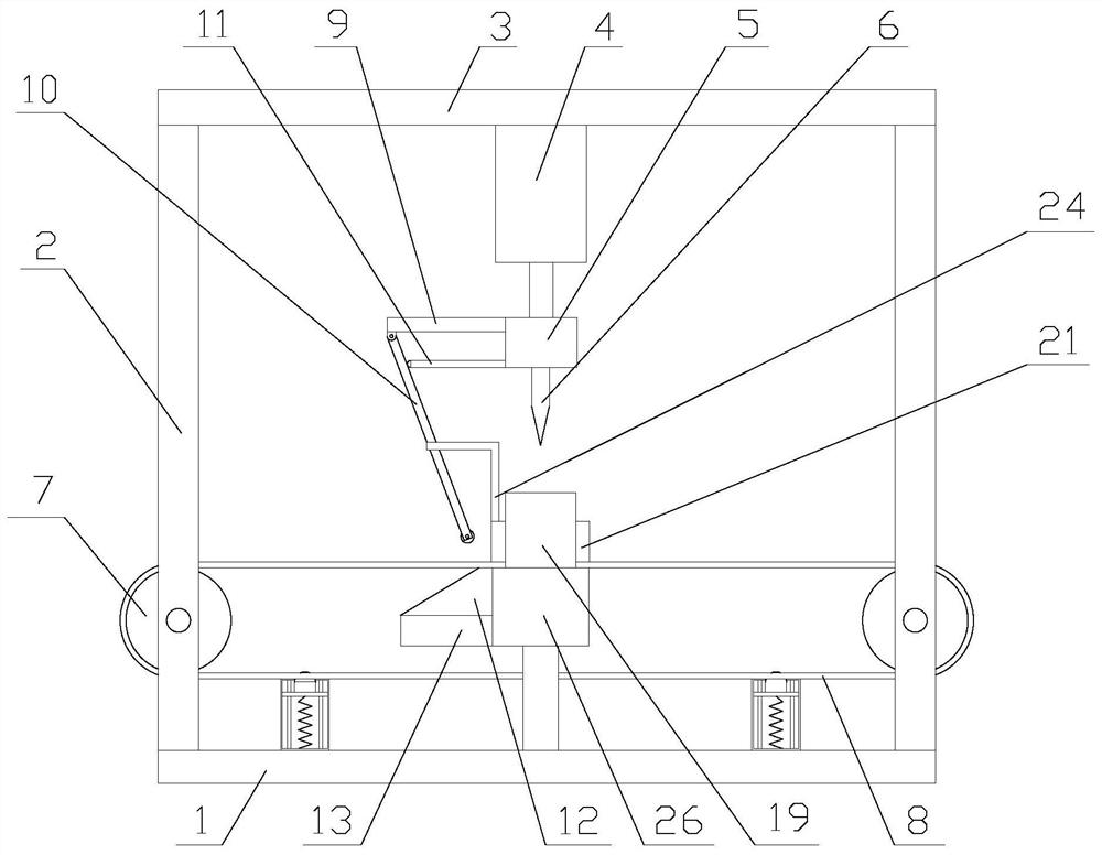
[0027] The present invention is described in further detail now in conjunction with accompanying drawing. These drawings are all simplified schematic diagrams, which only illustrate the basic structure of the present invention in a schematic manner, so they only show the configurations related to the present invention.

[0028] Such as figure 1 As shown, a continuous punching device with high precision includes a bracket, a punching mechanism, a positioning mechanism, a transmission mechanism and a clamping mechanism. The support rod 2 includes a base 1, a support rod 2 and a cross bar 3. There are two poles 2, and the two poles 2 are respectively arranged at the two ends of the base 1, the cross bar 3 is arranged above the base 1 through the two poles 2, and the punching mechanism is arranged on the cross bar 3, so The transmission mechanism is arranged on the pole 2, the clamping mechanism is arranged directly below the punching mechanism, and the positioning mechanism incl...


PUM


Abstract

The invention relates to a continuous hole punching device with high precision. The continuous hole punching device with high precision comprises a support frame, a hole punching mechanism, a positioning mechanism, a transmission mechanism and a clamping mechanism, wherein the hole punching mechanism is arranged on a transverse rod; the transmission mechanism is arranged on support rods; the clamping mechanism is arranged right under the hole punching mechanism; and the positioning mechanism comprises a moving assembly and a position clamping assembly. The continuous hole punching device withhigh precision has the advantages that the hole punching is realized through the hole punching mechanism; the transmission mechanism is positioned through the positioning mechanism, so that positioning on workpieces on a transmission belt is realized; clamping on the workpieces is realized through the clamping mechanism; and the hole punching precision is improved. Compared with an existing hole punching device, the continuous hole punching device with high precision has the advantages that through one output source, the linkage of hole punching, transmission and clamping of the workpieces isrealized; and the energy sources are saved. Compared with an existing positioning mechanism, the positioning mechanism uses a pure mechanical structure, avoids the use of a sensor, prolongs the service life, and improves the mechanism stability.

Description

technical field [0001] The invention relates to a high-precision continuous punching device. Background technique [0002] Punching refers to the operation of using a drill to process holes on solid materials. When batch punching is required, a punching machine is generally used to punch holes. First, the material is moved to the scanning area of ​​the camera of the automatic punching machine. After the camera scans the image Process and send signals to the control part. After the control part receives the signal, it further processes and controls the movement of the transmission part to make the punch move on the X-axis and Y-axis on the plane. After the movement is completed, the pneumatic part starts to work, and the electromagnetic The valve controls the cylinder to carry out the punching action to complete the punching. [0003] However, when the existing punching device is in use, the transmission, positioning and clamping of the workpiece all require different output...

Claims


Application Information

Patent Timeline
Patent Type & Authority Applications(China)
IPC IPC(8): B23B39/00B23B47/22B23Q7/00B23Q3/00
CPCB23B39/00B23Q3/00B23Q5/34B23Q7/00B23Q7/003
Inventor 李玉盛
Owner GUANGZHOU SONGBIN ENG TECH CO LTD
Learn More