A floating raft system for emergency drainage

A technology of floating rafts and drainage pumps, which is applied in the direction of life rafts, special-purpose ships, transportation and packaging, etc. It can solve the problems of intermittent drainage and achieve the effects of increasing drainage flow, enhancing drainage effect, and reducing the time required for drainage

Active Publication Date: 2022-06-07
SHANXI NORTH MACHINE BUILDING +1
View PDF17 Cites 0 Cited by
  • Summary
  • Abstract
  • Description
  • Claims
  • Application Information

AI Technical Summary

Problems solved by technology

[0003] The purpose of the present invention is to overcome the defects of the prior art, in order to solve the problem of discontinuous drainage caused by factors such as equipment deployment, extension of pipelines, water pumps and water, personnel wading to carry water pumps, complicated underwater conditions, etc. floating raft system

Method used


Image

  • A floating raft system for emergency drainage
  • A floating raft system for emergency drainage
  • A floating raft system for emergency drainage

Examples


Embodiment 1

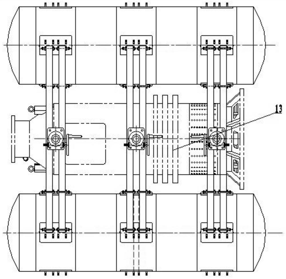
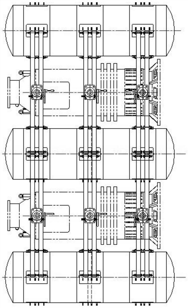
[0058] like Figure 2-3 As shown, it is a schematic diagram of the composition structure of the present invention, a floating raft system for emergency drainage, including: n drainage units, where n is a natural number; figure 2 is a floating raft system equipped with a single drainage pump, i.e. a floating raft system consisting of 1 drainage unit; image 3 It is a floating raft system equipped with two drainage pumps, that is, a floating raft system composed of 2 drainage units; and so on, a floating raft system composed of k drainage units, as long as the floating raft composed of k-1 drainage units system, it is enough to expand a beam frame structure and a drainage pump and a pontoon.

[0059] 1 drainage unit includes buoy 2, beam 5, lifting equipment, V-shaped positioning block 8, drainage pump 13;

[0060] a buoy 2 for providing buoyancy for the raft system in water;

[0061] The beam 5 is used to fix the buoy 2;

[0062] Lifting equipment, which is used to provide...

Embodiment 2

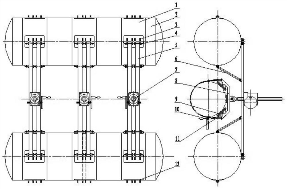
[0076] like Figure 1-3 As shown, a floating raft system for emergency drainage includes: n drainage units, where n is a natural number; 1 drainage unit includes a buoy support 1, a buoy 2, a fixed seat I3, a quick release mechanical pin 4, and a beam 5 , inclined beam 6, hand screw lift 7, V-shaped positioning block 8, rubber pad 9, tensioner 10, rubber pad base 11, fixed seat II12, drainage pump 13;

[0077] like Figure 5 As shown, the buoy support 1 is a cylindrical part used to fix the buoy 2 and the fixed seat I3;

[0078] like Figure 4 As shown, the buoy 2 is a cystic structure for providing buoyancy in the water; in order to meet the requirements of strength and light weight, this example is made of high-strength industrial polyester fiber material, which is provided with a groove for the buoy support 1;

[0079] like Image 6 and Figure 7 As shown, the fixed seat I3 and the fixed seat II12 are a special-shaped part, which are respectively used for the hinged fi...


PUM


Abstract

The invention relates to a floating raft system for emergency drainage, which belongs to the technical field of engineering machinery; it includes: n drainage units; one drainage unit includes a buoy (2), a beam (5), a lifting device, and a V-shaped positioning block ( 8), drainage pump (13); buoyancy drum is used for providing buoyancy; Beam is used for fixing buoy; Lifting device is used for providing lifting for V-shaped positioning block; V-shaped positioning block is used for fixing drainage pump (13), provides the drainage pump Lifting, so that the water inlet of the drainage pump is always under the water surface; the drainage pump is used for drainage; 2k buoys are evenly distributed on both sides of the beam, the V-shaped positioning block is fixed in the middle of the beam through the lifting equipment, and the drainage pump is fixed on the V-shaped positioning block. Compared with the prior art, the present invention reduces the complexity of the emergency drainage underwater situation, the danger of manually wading and carrying the drainage pump, and the high labor intensity, and improves the drainage flow through modular expansion, reducing the time required for drainage; greatly reducing the original manual labor. Disadvantages of handling the drainage pump, optimizing the drainage effect.

Description

technical field [0001] The invention relates to a floating raft system for emergency drainage and belongs to the technical field of construction machinery. Background technique [0002] With the shortage of resources, the deepening of coal mining, and the increasingly complex hydrogeology, mine water damage has become one of the disasters that threaten the safety of mine production. In recent years, all kinds of major flooding accidents in the country have become the second largest disaster in the process of coal mining due to untimely rescue and difficult rescue, threatening the safety of miners and causing serious losses to national property. Often after a flooding accident occurs, we can only resort to traditional rescue methods. This method is extremely susceptible to equipment deployment, extension of pipelines, water pumps to follow water, personnel wading through water to carry pumps, and complicated underwater conditions, resulting in intermittent drainage. This lea...

Claims


Application Information

Patent Timeline
Patent Type & Authority Patents(China)
IPC IPC(8): B63B35/00B63C9/04E21F11/00B66F3/00B66F3/08
CPCB63B35/00B63C9/04E21F11/00B66F3/00B66F3/08
Inventor 雷云龙李有生赵瑜李向南侯佳峰陈栋刘庚解军昌郝桂欣张宁
Owner SHANXI NORTH MACHINE BUILDING
Why Eureka
Try Eureka