Fuse-plug dam section test method using overflow water tank synchronous stacking narrow groove and pipe

A test method and flow tank technology, applied in hydraulic models and other directions, can solve the problems of dissimilar materials and dissimilarity of test water supply flow, and achieve the effects of low cost, small water consumption and simple test method.

Inactive Publication Date: 2020-10-09
叶兴
View PDF0 Cites 0 Cited by
  • Summary
  • Abstract
  • Description
  • Claims
  • Application Information

AI Technical Summary

Problems solved by technology

[0006] Purpose of the present invention: to invent new test equipment to solve the difficult problem that existing indoor and outdoor test equipment test water supply flow, upstream water level are not similar to actual engineering, solve the prototype test water supply problem; invent new test method to solve existing test method material dissimilarity Difficulties, especially in resolving the controversial "consolidated clay" test

Method used


Image

  • Fuse-plug dam section test method using overflow water tank synchronous stacking narrow groove and pipe
  • Fuse-plug dam section test method using overflow water tank synchronous stacking narrow groove and pipe
  • Fuse-plug dam section test method using overflow water tank synchronous stacking narrow groove and pipe

Examples


Embodiment 1

[0023] Example 1: A test example of a self-collapsing dam with a parent clay core wall of sub-geotechnical anti-seepage panels. There are many new self-collapsing dams to be tested in a certain watershed. If the new self-collapsing dams are low and the water supply meets the requirements of the overall test, the prototype test of the overall section can be carried out; It is necessary to carry out the top local prototype narrow groove test to find out the water head required for the safe cutting rate at the top of the mother clay core wall and the burst time of the sub-self-collapsible dam; The local prototype of the clay anti-seepage body has been compressed and narrowed in layers to obtain the self-rupture dam burst process. details as follows:

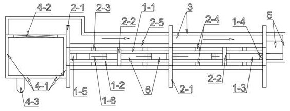
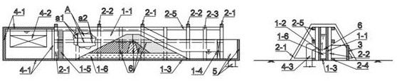
[0024] The self-collapsing dam section test method of the overflow tank synchronously stacked with narrow groove pipes, which utilizes the overflow water tank synchronously stacked open narrow grooves and the overflow water tank is...

Embodiment 2

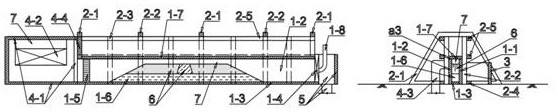
[0028] Example 2: A cross-sectional test example of a self-collapsing embankment with a flooded clay core wall. If the self-collapsing dam is low and the water supply for the overall test meets the requirements, the overall cross-section prototype test can be carried out; if the self-collapsing dam is high, the downstream flood control does not require the process of self-collapsing dam collapse, and only the local prototype narrow groove test on the top is needed to find out the clay core. The water head and burst time required for the safe cutting rate at the top of the wall; if the self-collapsing dam is high, the prototype cross-section test cannot meet the water supply requirements, and the downstream flood control requires the self-collapsing dam burst process, and the local prototype of the clay anti-seepage body has compression narrowing tube, obtained from the dam burst process.


PUM


Abstract

The invention relates to a fuse-plug dam section test method using an overflow water tank synchronous stacking narrow groove and pipe, and belongs to the technical field of hydraulic prototype tests and model tests. The method involves an overflow water tank synchronous stacking open narrow groove comprising a synchronous stacking narrow groove, a support frame, a water return groove (3), an overflow high-level water tank, a water return well (5) and a test section (6), and the overflow water tank synchronous stacking pressure narrow pipe additionally provided with a pressing plate (1-7), a water injection pipe (1-8) and a partition plate (4-4). The fuse-plug dam section test method comprises a clay impervious body local prototype narrow groove test (F-1), a clay impervious body local prototype pressure narrow pipe (F-2), a non-viscous easily-washed gravel-soil dam body local prototype narrow groove test (F-3), an undisturbed consolidated clay grooving test (F-4) and a fuse-plug dam overall prototype narrow groove test (F-5). The method is suitable for flood fuse-plug dam experimental study, the test is simple, the manufacturing cost is low, and the test result is free of scale reduction effect.

Description

technical field [0001] The invention belongs to the technical field of hydraulic prototyping and model testing, and also belongs to the technical field of dike and dam extreme flood diversion engineering technology, and specifically relates to a self-collapsing dam section test method in which overflow water tanks are synchronously stacked with narrow groove pipes. Background technique [0002] In 2017, the main and auxiliary spillways of the Oloville Reservoir, which has the highest dam in the United States, were in danger at the same time. This not only exposed the maintenance and repair problems commonly faced by exposed concrete, but also sounded the safety alarm for single-spillway reservoirs. In Brazil in 1997, the gate operator left the power plant for lunch, which caused the Da Cunha dam to burst when it was full and the downstream dams to fail in a chain. Since the 1930s, there have been 8 hafnium dams and 7 earth-rock dam explosion cases. In particular, the geosyn...

Claims


Application Information

Patent Timeline
Patent Type & Authority Applications(China)
IPC IPC(8): E02B1/02
CPCE02B1/02
Inventor 叶兴杨旭
Owner 叶兴
Why Eureka
Try Eureka