Sliding door arrangement

A sliding door and facility technology, applied in the direction of windows/doors, door/window accessories, power control mechanisms, etc., can solve problems such as lowering of lifting magnets, and achieve the effect of reducing electrical wiring, reducing structural space, and compact structure

Pending Publication Date: 2020-10-09
DORMAKABA DEUT GMBH
View PDF0 Cites 1 Cited by
  • Summary
  • Abstract
  • Description
  • Claims
  • Application Information

AI Technical Summary

Problems solved by technology

It has proven to be disadvantageous in this locking device that the force

Method used


Image

  • Sliding door arrangement
  • Sliding door arrangement
  • Sliding door arrangement

Examples


Example Embodiment

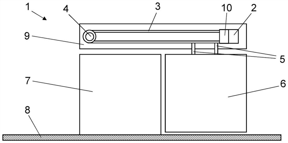
[0055] in figure 1 A schematic diagram of the sliding door facility 1 is shown in. The sliding door installation 1 includes a sliding door element 6 and a door driver 9, via which the sliding door element 6 can be moved in a motor-driven manner, for example in figure 1 Movement between the closed position shown in and the open position in which the sliding door element 6 is arranged in the door opening, and in the open position the sliding door element 6 is at least partially arranged in the wall element 7 Rear and release the door opening here. According to one embodiment, the door driver 9 is arranged above the sliding door element 6 of the sliding door installation 1. However, it is also conceivable that the door drive 9 is alternatively arranged under the sliding door element 6, for example between the sliding door element 6 and the floor 8 or in the floor 8 under the sliding door element 6.

[0056] The door driver 9 of the sliding door installation 1 includes an electric m...


PUM


Abstract

The invention relates to a sliding door arrangement comprising: a door drive having a traction mechanism, in particular a belt, a rope or a chain; a sliding door travel mechanism having a movable travel carriage for the sliding door element, which travel carriage is coupled to the traction mechanism and can be moved from a closed position into at least one predetermined open position via a path; and a locking device used for locking the door drive, wherein the locking device has at least one locking mechanism, the locking mechanism can move back and forth between a release position and a locking position, a locking section of the locking mechanism interacts with the traction mechanism in a force-fitting and/or form-fitting manner in a locking position in such a way that the travel carriagecoupled to the traction mechanism is locked, and the locking device has a linear motor for displacing the locking mechanism between a release position and a locking position.

Description

Technical field [0001] The present invention relates to a sliding door installation, comprising: a door driver having a traction mechanism, especially a belt, rope or chain; a sliding door running mechanism, the sliding door running mechanism having a movable sliding door element A walking carriage, which is coupled to the traction mechanism and can move from the closed position to at least one predetermined opening position via a section; and a locking device for locking the door driver. Background technique [0002] In such sliding door installations, the locking device is usually provided on the reversing roller for the traction mechanism. Such reversing rollers are typically arranged on the side of the door drive opposite to the traction mechanism drive, which drives the traction mechanism. For locking, the reversing roller is blocked by a locking element, for example by a toothed locking disc. Such locking devices typically have relatively large space requirements. In ord...

Claims


Application Information

Patent Timeline
IPC IPC(8): E06B3/46E05F15/643E05D15/06E05B65/08E05B47/00E05B15/00E05C19/00
CPCE06B3/4636E05F15/643E05D15/0626E05B65/08E05B47/0012E05B47/0001E05B15/00E05C19/00E05Y2900/132E05F15/60E05Y2201/22E05Y2201/246E05Y2201/43E05Y2201/42E05Y2201/442E05Y2201/638E05Y2201/648E05Y2201/652E05Y2800/296E05Y2800/266E05B47/0006
Inventor 斯文·布施马丁·瓦格纳马蒂亚斯·德吕安德烈亚斯·芬克
Owner DORMAKABA DEUT GMBH
Why Eureka
Try Eureka