Supercharge Your Innovation With Domain-Expert AI Agents!

Shaft sleeve for simulating supercritical CO2 fracturing sample and use method

A supercritical and fracturing technology, applied in wellbore/well components, teaching models, earth-moving drilling and production, etc., can solve the problem of inability to achieve single-stage multi-perforation fracturing, etc., to improve accuracy, sealing effect, test Easy operation and high success rate

Active Publication Date: 2020-10-09
NORTHEASTERN UNIV
View PDF9 Cites 6 Cited by
  • Summary
  • Abstract
  • Description
  • Claims
  • Application Information

AI Technical Summary

Problems solved by technology

The former has higher requirements for samples; the latter has no detailed description of wellbore details, but neither of them can meet the experimental requirements of single-stage multi-perforation fracturing, and the measured temperature is not the bottom hole temperature
The fifth type is the wellbore casing with multiple perforations. The second method above is still used to bond the hole in the center of the sample and the wellbore, and the perforation is filled with paper balls or adhesive tape to prevent the glue from blocking the hole. There are still problems similar to the second method

Method used


Image

  • Shaft sleeve for simulating supercritical CO2 fracturing sample and use method
  • Shaft sleeve for simulating supercritical CO2 fracturing sample and use method
  • Shaft sleeve for simulating supercritical CO2 fracturing sample and use method

Examples


Embodiment 1

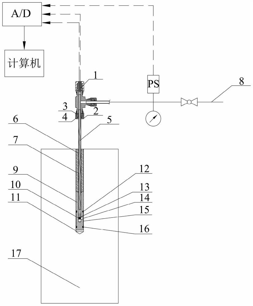
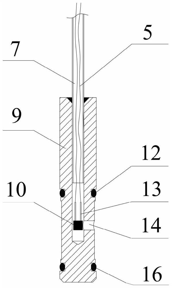
[0034] like figure 1 , 2 shown, for simulating supercritical CO 2 The wellbore casing of the single-section annular chamber of the fracturing sample includes an outer pipe 9, a central liquid injection pipe 7, a seal and a miniature temperature sensor. The outer tube 9 is made of high-pressure resistant stainless steel; the outer diameter of the outer tube 9 is adapted to the diameter of the central borehole 11 of the sample 17; the channel of the central liquid injection tube 7 is drilled along the central axis of the outer tube 9 , the channel diameter is 3.2mm, and the bottom of the channel is 10mm away from the bottom of the outer tube 9; the groove depth of the upper annular groove 12 and the lower annular groove 16 is 1.4mm, and the groove width is 2.2mm. The outer diameters of the upper annular groove 12 and the lower annular groove 16 are the same as the outer diameter of the outer tube 9, and the inner diameter is larger than the outer diameter of the central liquid...

Embodiment 2

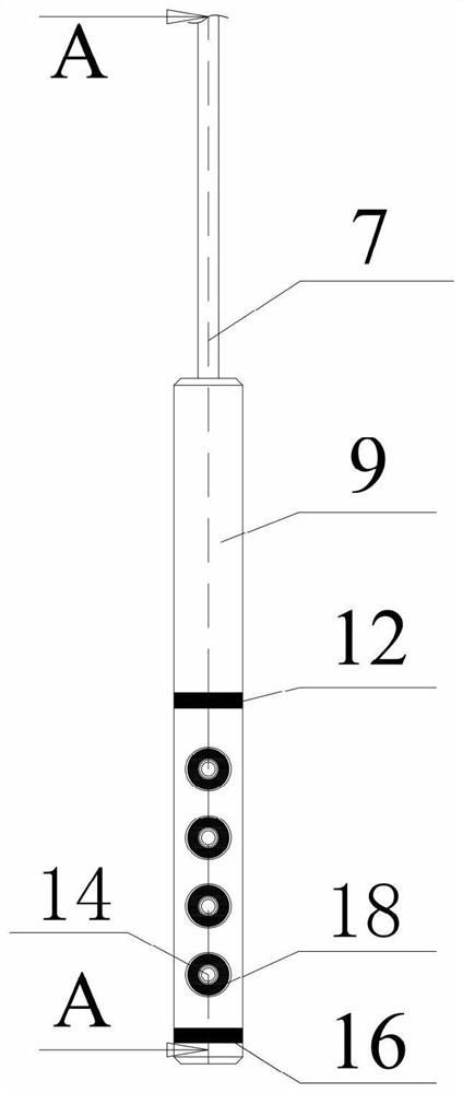
[0042] like image 3 , 4 As shown, the difference from Embodiment 1 is that the wellbore casing with single-segment straight rows and multiple perforations: at the position d1 from the upper end face of the lower annular groove 16 of the outer pipe 9, The side wall is provided with the first circular groove 18, and based on the position of the first circular groove 18, move up along the axis direction (d1+h) to open the second round groove 18; similarly, move up along the axis direction (d1 +2h) position to open a third circular groove 18, move up along the axis direction (d1+3h) to open a fourth circular groove 18, and in the first circular groove 18, the second circular groove 18, the third A fifth circular groove 18 , a sixth circular groove 18 , a seventh circular groove 18 , and an eighth circular groove 18 are provided in a linear array opposite the circular groove 18 and the fourth circular groove 18 . Wherein, the outer diameter of each circular groove 18 is R1, the ...

Embodiment 3

[0044] like Figure 5 , 6 As shown, the difference from Example 1 is that the single-stage helical multi-perforated wellbore casing: the position away from the upper end surface d1 of the lower annular groove 16 of the outer pipe 9 is on the side of the outer pipe 9 The first circular groove 18 is opened on the wall, and based on the position of the first circular groove 18, move up (d1+h) along the axis direction and rotate 90° counterclockwise in the radial direction to open the second circular groove 18; similarly , move up along the axis direction (d1+2h) and rotate counterclockwise 90° radially to open the third round groove 18, move up along the axis direction (d1+3h) and rotate 90° counterclockwise radially to open the fourth circular groove 18 18 round grooves. Wherein, the outer diameter of each circular groove 18 is R1, the inner diameter is R2, and the center of each circular groove 18 is drilled with a liquid injection hole 14 whose diameter is smaller than R2. ...


PUM


Abstract

The invention relates to a shaft sleeve for simulating a supercritical CO2 fracturing sample and a use method. According to the technical solution, the device comprises an outer pipe, a central liquidinjection pipe, sealing elements and miniature temperature sensors, wherein the liquid injection channel is formed in the center of the outer pipe, one end of the central liquid injection pipe is welded to the inner wall of the outer pipe, the other end of the central liquid injection pipe is connected with a supercritical CO2 injection end, a pressure sensor is arranged on a pipeline between thecentral liquid injection pipe and the supercritical CO2 injection end, an upper side annular groove and a lower side annular groove are formed in the outer wall of the outer pipe, liquid injection holes are formed between the upper side annular groove and the lower side annular groove, the number, the angles, the positions and the fracturing modes of the liquid injection holes are set according to test requirements, the liquid injection holes communicate with the liquid injection channel, the sealing elements are arranged in the upper side annular groove and the lower side annular groove, andthe miniature temperature sensors are arranged at the positions of the liquid injection holes. According to the shaft sleeve, single-section fracturing or single-section multi-perforation synchronoustargeted fracturing can be achieved at the designated layer, and the phase change of CO2 in the fracturing process can be synchronously monitored in real time.

Description

technical field [0001] The invention belongs to the technical field of material cracking test, in particular to a method for simulating supercritical CO 2 Wellbore casing for fracturing samples and its use. Background technique [0002] Horizontal drilling and hydraulic fracturing are the main methods of extracting shale gas. The application of hydraulic fracturing technology consumes a lot of water resources. As an alternative to conventional water-based fracturing fluids, supercritical CO 2 It has gradually become a very promising anhydrous fracturing fluid. When CO 2 When the temperature and pressure exceed its critical value (31.1°C, 7.38MPa) at the same time, it is a supercritical state. Supercritical CO 2 It has unique physical and chemical properties, such as low viscosity, close to zero surface tension, large diffusion coefficient, and super solvency, etc. These unique properties make it stand out in unconventional reservoir volume fracturing effects . Due to...

Claims


Application Information

Patent Timeline
IPC IPC(8): E21B43/26E21B47/06E21B43/116E21B43/119E21B47/00G09B25/04
CPCE21B43/116E21B43/119E21B43/26E21B47/00E21B47/06G09B25/04
Inventor 朱万成张秀凤魏晨慧徐曾和刘书源于永军侯晨
Owner NORTHEASTERN UNIV
Features
  • R&D
  • Intellectual Property
  • Life Sciences
  • Materials
  • Tech Scout
  • Unparalleled Data Quality
  • Higher Quality Content
  • 60% Fewer Hallucinations
Learn More