Supercritical carbon dioxide recompression cycle power generation system and operation method

A carbon dioxide, cyclic power generation technology, applied in machines/engines, steam engines, mechanical equipment, etc., can solve problems such as inability to adjust, and achieve the effect of reducing failure rate, wide application range, and reducing complexity

Pending Publication Date: 2020-10-09
HANGZHOU STEAM TURBINE
View PDF0 Cites 16 Cited by
  • Summary
  • Abstract
  • Description
  • Claims
  • Application Information

AI Technical Summary

Problems solved by technology

[0003] The purpose of this application is to provide a supercritical carbon dioxide recompression cycle power generation system and operation method, which solves the...

Method used


Image

  • Supercritical carbon dioxide recompression cycle power generation system and operation method

Examples


Embodiment 1

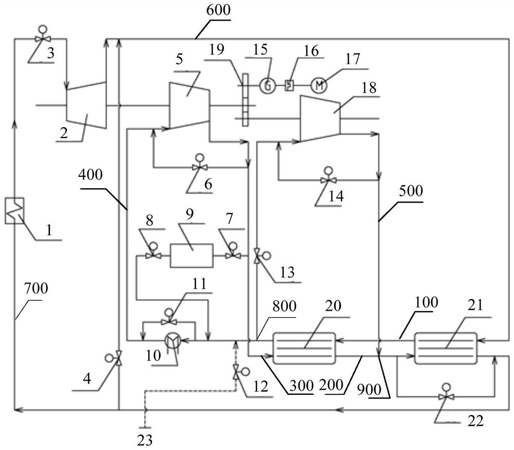
[0034] see figure 1 As shown, the embodiment of the present application provides a supercritical carbon dioxide recompression cycle power generation system, including: a heat exchange path, a first compression path 400, a second compression path 500, a heat absorption path 700, a work output path 600 and a return path Heat path 300; wherein, the heat exchange path includes a first heat exchange path 100 and a second heat exchange path 200; the first compression path 400 is arranged in parallel with the second compression path 500 and forms the same input end 800, and the first compression path 400 merges with the second compression path 500 via the heat recovery path 300 and forms the same output end 900;

[0035] The output end of the first heat exchange path 100 is connected with the same input end 800, and the same output end 900 is connected with the input end of the second heat exchange path 200; the output end of the second heat exchange path 200, the heat absorption pat...

Embodiment 2

[0068] Embodiments of the present application also provide a method for operating a supercritical carbon dioxide recompression cycle power generation system, which is applied to the supercritical carbon dioxide recompression cycle power generation system in any of the above embodiments, including the following steps (the symbols therein refer to Embodiment 1) :

[0069] When the supercritical carbon dioxide recompression cycle power generation system is running at reduced load, the speed of each rotating part remains unchanged, open the turbine bypass valve 4 and gradually close the valve port of the turbine throttle valve 3, so that a part of the working fluid passes through the flow bypass It flows to the outlet of turbine 2 and mixes with its exhaust gas; when the supercritical carbon dioxide recompression cycle power generation system is operating with increased load, the speed of each rotating part remains unchanged, and the turbine bypass valve 4 is closed and the turbine...


PUM


Abstract

The invention relates to the technical field of power generation, in particular to a supercritical carbon dioxide recompression cycle power generation system and an operation method. The system comprises a first heat exchange path, a second heat exchange path, a first compression path, a second compression path, a heat absorption path, a work output path and a heat return path, wherein the first compression path and the second compression path are arranged in parallel and form the same input end, and the first compression path and the second compression path are converged through the heat return path and form the same output end; the output end of the first heat exchange path communicates with the same input end, and the same output end communicates with the input end of the second heat exchange path; the output end of the second heat exchange path, the heat absorption path and the input end of the work output path sequentially communicate with one another; and the output end of the work output path communicates with the input end of the first heat exchange path, the work output path is provided with a turbine, and a circulation bypass provided with a turbine bypass valve is formedbetween the outlet end of the turbine and the heat exchange paths.

Description

technical field [0001] The present application relates to the technical field of power generation, in particular to a supercritical carbon dioxide recompression cycle power generation system and an operation method. Background technique [0002] At present, as a cutting-edge power generation technology, the supercritical carbon dioxide Brayton cycle has broad engineering application prospects in the fields of thermal power, nuclear power, ship power and solar power generation. There are the following key problems: Due to the closed cycle, the flow, speed, and pressure of rotating machinery usually have a coupling relationship, so it is difficult to adjust the operating state of a single component, which increases the complexity of matching operation of various rotating components under variable operating conditions of the system , that is, the existing supercritical carbon dioxide Brayton cycle system cannot quickly self-adjust to the working conditions of load changes. Co...

Claims


Application Information

Patent Timeline
IPC IPC(8): F01K7/32F01K13/00F01K13/02F01K21/00F01K25/10F01D15/10
CPCF01D15/10F01K7/32F01K13/00F01K13/02F01K21/00F01K25/103
Inventor 高骥丁旭东张军辉刘象拯马晓飞杨雄民毛汉忠孔建强谢永慧
Owner HANGZHOU STEAM TURBINE
Why Eureka
Try Eureka