Scroll type compressor
一种压缩机、涡旋型的技术,应用在涡旋型压缩机领域,能够解决动力损失等问题,达到减少动力损失的效果
- Summary
- Abstract
- Description
- Claims
- Application Information
AI Technical Summary
Problems solved by technology
Method used
Image

Examples
Embodiment 1
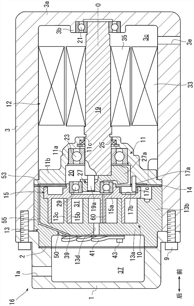
[0062]The scroll compressor of embodiment 1 such as figure 1 Shown is an electric compressor. This electric compressor includes a scroll compression mechanism 10 , a motor mechanism 12 and a housing 16 . The housing 16 has a front housing 1 and a motor housing 3 .
[0063] In the instructions below, the figure 1 The front housing 1 side on the left side of the paper is defined as the front side of the electric compressor, which will be located figure 1 The motor housing 3 side on the right side of the paper is defined as the rear side of the electric compressor. and, figure 2 The front and rear directions shown in the subsequent figures all correspond to the figure 1 express. In addition, the front-back direction in Example 1 is an example. The front-rear direction of the electric compressor is appropriately changed according to the vehicle on which it is mounted.
[0064] like figure 1 As shown, the front housing 1 and the motor housing 3 are butted against each oth...
Embodiment 2
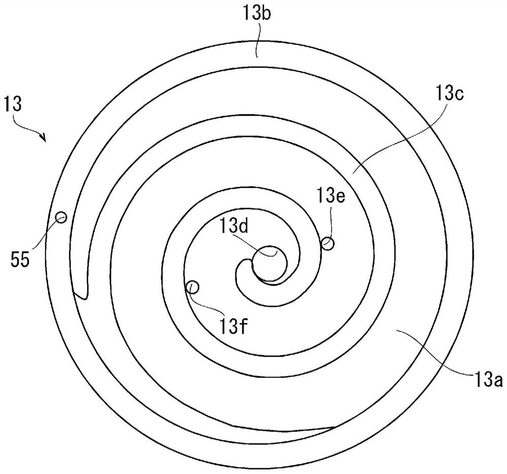
[0093] In the electric compressor of embodiment 2, such as Image 6 As shown, the subports 13e and 13f in the first embodiment are not formed on the fixed substrate 13a. Therefore, the reed valve 39 does not have the auxiliary valve parts 39b, 39c like the first embodiment either. In addition, the holder 41 does not have the sub-holder parts 41b, 41c like the first embodiment, either. The other configurations are the same as those in Embodiment 1, and the same reference numerals are attached to the same configurations, and detailed descriptions of the configurations are omitted.
[0094] In this electric compressor, the air supply passage 60 moves the liquid refrigerant and lubricating oil that may exist in the compression chamber 31 to the back pressure chamber 20 . The discharge passage functions as a subport for discharging the liquid refrigerant to prevent shock caused by pressurizing the liquid, and thus the subports 13e and 13f can be omitted. Therefore, by reducing t...
Embodiment 3
[0096] In the electric compressor of embodiment 3, such as Figure 7 As shown, a discharge hole 62 communicating with the back pressure chamber 20 and a valve chamber 64 communicating with the discharge hole 62 are formed in the fixed scroll 13 . The periphery of the portion of the valve chamber 64 that communicates with the discharge hole 62 is formed as a valve seat 64 a. In addition, the valve chamber 64 is covered by the gasket 2 having the opening 2a. The periphery of the opening 2a of the washer 2 is formed as a spring seat 2b. In addition, the opening 2 a and the valve chamber 64 communicate with the discharge chamber 37 through a groove 2 c recessed in the gasket 2 .
[0097] A ball valve 44 as a check valve is provided in the valve chamber 64 on the side of the valve seat 64a, and the urging spring 42 is provided between the ball valve 44 and the spring seat 2b. The discharge hole 62 , the valve chamber 64 , the opening 2 a and the groove 2 c correspond to the disc...
PUM
 Abstract
Description
Claims
Application Information
 - R&D
- Intellectual Property
- Life Sciences
- Materials
- Tech Scout
- Unparalleled Data Quality
- Higher Quality Content
- 60% Fewer Hallucinations
Browse by: Latest US Patents, China's latest patents, Technical Efficacy Thesaurus, Application Domain, Technology Topic, Popular Technical Reports.
© 2025 PatSnap. All rights reserved.Legal|Privacy policy|Modern Slavery Act Transparency Statement|Sitemap|About US| Contact US: help@patsnap.com