
Vibration Dampers and Vehicles

A technology for vibration dampers and motor vehicles, applied in shock absorbers, vehicle springs, vehicle components, etc., can solve the problems of expensive and complicated vibration dampers, and achieve the effect of reducing the number of flow paths and valves

Active Publication Date: 2022-05-10
THYSSENKRUPP BILSTEIN +1
View PDF7 Cites 0 Cited by
  • Summary
  • Abstract
  • Description
  • Claims
  • Application Information

AI Technical Summary

Problems solved by technology

Such vibration dampers are very complex, so they are more expensive than traditional vibration dampers

Method used


Image

  • Vibration Dampers and Vehicles
  • Vibration Dampers and Vehicles
  • Vibration Dampers and Vehicles

Examples


Embodiment Construction

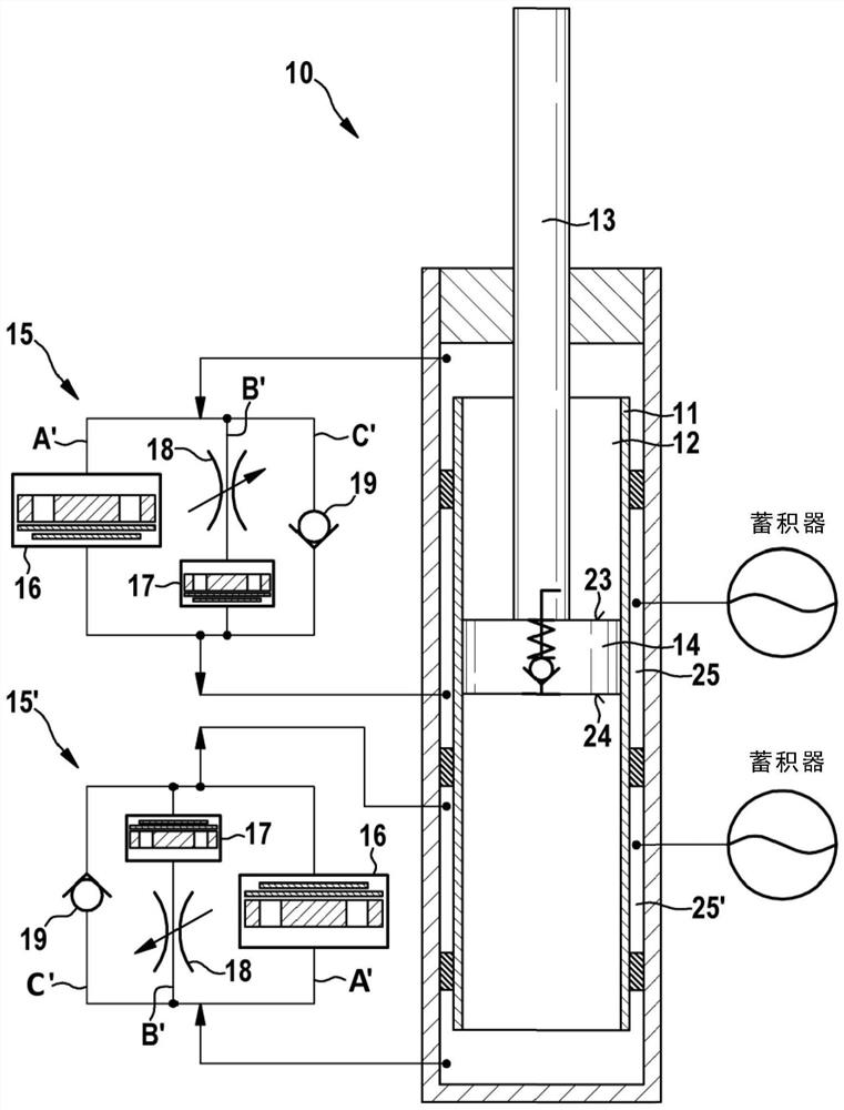
[0039] figure 1 A schematic diagram of the vibration damper 10 is shown. The vibration damper 10 includes a damper tube 11 . The damping tube 11 contains at least one damping fluid 12 . A piston rod 13 with a piston 14 is guided axially in the damping tube 11 . The piston 14 divides the damper tube 11 into two fluid regions. The first fluid zone adjoins the piston ring surface 23 and the second fluid zone adjoins the piston surface 24 . In other words, the first fluid zone is close to the piston rod 13 and the second fluid zone is remote from the piston rod 13 . The vibration damper 10 comprises two valve units 15, 15'.

[0040] If the subassembly formed by the piston rod 13 and the piston 14 and the damper tube 11 are moved relative to each other such that the volume of the second fluid region adjoining the piston surface 24 decreases, it can be said to be a compression phase. If the subcomponents are moving in the opposite direction, it can be said to be a rebound phas...


PUM


Abstract

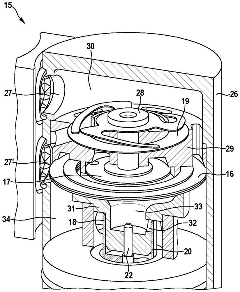
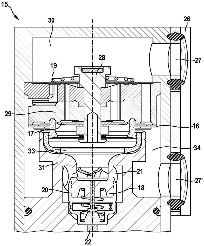
The present invention relates to vibration dampers and vehicles. The invention relates to a vibration damper for a motor vehicle, the vibration damper having at least one damping tube (11), a piston rod (13) and at least one valve unit (15), the damping tube (11) comprising at least one damping fluid (12), the piston rod (13) has a piston (14) guided axially in the damping tube (11), wherein the valve unit (15) comprises at least three flow paths for the damping fluid (12) ( A', B', C'), the first flow path (A') includes the first valve (16) for the first damping setting, the second flow path (B') includes the second valve (16) for the second damping setting valve (17) and variable throttle valve (18), and the third flow path (C') includes a check valve (19), wherein the second damping setting is softer than the first damping setting, and the second flow path (B ') can be at least partially adjusted by a variable throttle valve (18).

Description

technical field [0001] The present invention relates to vibration dampers. Furthermore, the invention relates to a vehicle having such a vibration damper. Background technique [0002] A vibration damper of the type mentioned is known, for example, from DE 10 2005 053 394 A1. [0003] DE 10 2005 053 394 A1 describes a vibration damper with a cylinder surrounded by a tube. A piston rod with a piston is arranged in the cylinder. In addition, the vibration damper includes two adjustable damping valves. An adjustable damper valve is arranged externally on the vibration damper and is fluidly connected to the cylinder. An adjustable damping valve allows for adaptation of the damping during the compression and rebound phases of the vibration damper. More precisely, it can switch between hard and soft damping as needed. The use of check valves enables the flow of damping fluid between the two damping valves to be clearly linked to the stages. [0004] In the prior art describ...

Claims


Application Information

Patent Timeline
Patent Type & Authority Patents(China)
IPC IPC(8): F16F9/46F16F9/34B60G17/08
CPCF16F9/46F16F9/34B60G17/08B60G2202/24F16F9/3484F16F9/464F16F9/325B60G13/06B60G2206/41B60G2500/114B60G2800/162F16F9/348F16F9/19F16F9/516F16F2228/066F16K15/148F16F2222/12F16K11/22
Inventor 弗雷迪·沃纳塔
Owner THYSSENKRUPP BILSTEIN
Learn More