Electricity-heat-gas comprehensive energy system for protective suit microenvironment

A comprehensive energy system and micro-environment technology, applied in protective clothing, electrical components, machines using electric/magnetic effects, etc., can solve problems such as bulky and bulky system configuration, complex external mechanisms, and lack of storage design, etc., to improve the environment The effect of comfort and working convenience conditions, high integration and compact structure

Pending Publication Date: 2020-10-09
UNIV OF ELECTRONICS SCI & TECH OF CHINA
View PDF16 Cites 2 Cited by
  • Summary
  • Abstract
  • Description
  • Claims
  • Application Information

AI Technical Summary

Problems solved by technology

[0004] In terms of microenvironment adjustment function, although the research and development and practical development of various new protective clothing and related technical means have made great progress, the key scientific theories and practical technical problems that have not yet been resolved are still relatively prominent, mainly reflected in the following aspects: : First, all kinds of new protective clothing and related technical means are adjustment measures taken for a certain parameter index in the temperature, humidity, and airflow parameters of the microenvironment of the protective clothing, and lack comprehensive consideration of the microenvironmental temperature, humidity, and airflow. Overall control design; Second, although various new types of protective clothing and related technical means integrate high-energy-density secondary batteries that can store electric energy, they lack design for heat storage, recycling of waste heat and cold, and lack of The mutual conversion between multiple energy sources and the low utilization efficiency of comprehensive energy limit the effective working time of protective clothing; third, the external mechanisms of various new protective clothing and related technologies are relatively complicated, and the system composition is bloated and cumbersome, which is difficult to wear and operate. Mobile utility is limited

Method used


Image

  • Electricity-heat-gas comprehensive energy system for protective suit microenvironment
  • Electricity-heat-gas comprehensive energy system for protective suit microenvironment
  • Electricity-heat-gas comprehensive energy system for protective suit microenvironment

Examples


Embodiment

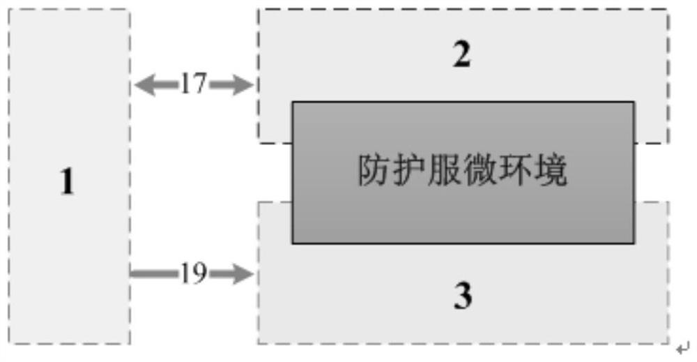
[0022] figure 1 It is a principle block diagram of an electric-heat-gas comprehensive energy system used in the protective clothing microenvironment of the present invention.

[0023] In this example, if figure 1 As shown, the present invention is an electric-heat-gas integrated energy system for the microenvironment of protective clothing, including: an electric energy device 1 , a thermal energy device 2 and an airflow device 3 . Among them, the electric energy device 1 realizes the electric energy supply to the thermal energy device 2 and the electric energy recovery from the thermal energy device 2 through the bidirectional interface circuit 17; secondly, the electric energy device 1 supplies electric energy to the airflow device 3 through the one-way circuit interface 19; the thermal energy device 2 pairs The temperature parameters of the micro-environment of the protective clothing are mainly adjusted; the airflow device 3 is mainly adjusted for the airflow and humidity...


PUM


Abstract

The invention discloses an electricity-heat-gas comprehensive energy system for a protective suit microenvironment. Main body adjustment of airflow and humidity parameters of the microenvironment is achieved through a purification and ventilation function of an airflow device, and main body adjustment of temperature parameters of the protective suit microenvironment can be actively performed through bidirectional refrigeration / heating of a heat energy device. The heat energy device and the airflow device achieve microenvironment integral regulation and control aiming at the body surface humidity and somatosensory temperature of a wearer and the fresh air supply. The system has the advantages of high integration level, compact structure and portability and completeness, and can effectivelyimprove the environmental comfort and working convenience for protective suit wearing operators.

Description

technical field [0001] The invention belongs to the technical field of protective clothing, and more specifically relates to an electric-heat-gas comprehensive energy system used in the microenvironment of protective clothing. Background technique [0002] Existing protective clothing products that focus on barrier properties and mechanical flexibility have less communication between the internal environment and the external environment, and usually present a relatively airtight and isolated independent microenvironment. In the face of actual working environments such as biological pollution, nuclear, biological and chemical, toxic dust, high temperature, high humidity, and extreme cold, the protected personnel often need to wear protective clothing for a long time to carry out work tasks. Therefore, the internal microenvironment of protective clothing has an important impact on the physical and mental health, work efficiency and work accidents of workers. [0003] The micr...

Claims


Application Information

Patent Timeline
Patent Type & Authority Applications(China)
IPC IPC(8): F25B21/02F28D20/02H02J7/00H02J7/32A41D13/00A41D13/002A41D13/005A41D27/02A41D27/20
CPCA41D13/0012A41D13/002A41D13/0025A41D13/0051A41D13/0053A41D27/02A41D27/20A41D2400/12F25B21/02F25B2321/0252F28D20/021H02J7/0063H02J7/0068H02J7/32H02J2207/20Y02E60/14
Inventor 谢鸿钦陈路锋宋广奎邱静程洪
Owner UNIV OF ELECTRONICS SCI & TECH OF CHINA
Why Eureka
Try Eureka