Low-pressure egr system with turbo bypass

A technology of turbine and conduction system, applied in charging system, mechanical equipment, engine operation, etc., can solve the problems of insufficient combustion of filter particle quality and low oxygen content, and achieve the effect of increasing oxygen content, shortening regeneration interval, and achieving and efficiency effects

Active Publication Date: 2020-10-09
TENNECO
View PDF9 Cites 0 Cited by
  • Summary
  • Abstract
  • Description
  • Claims
  • Application Information

AI Technical Summary

Problems solved by technology

Since most gasoline engines run stoichiometrically, the oxygen content in the exha

Method used


Image

  • Low-pressure egr system with turbo bypass
  • Low-pressure egr system with turbo bypass
  • Low-pressure egr system with turbo bypass

Examples


Embodiment Construction

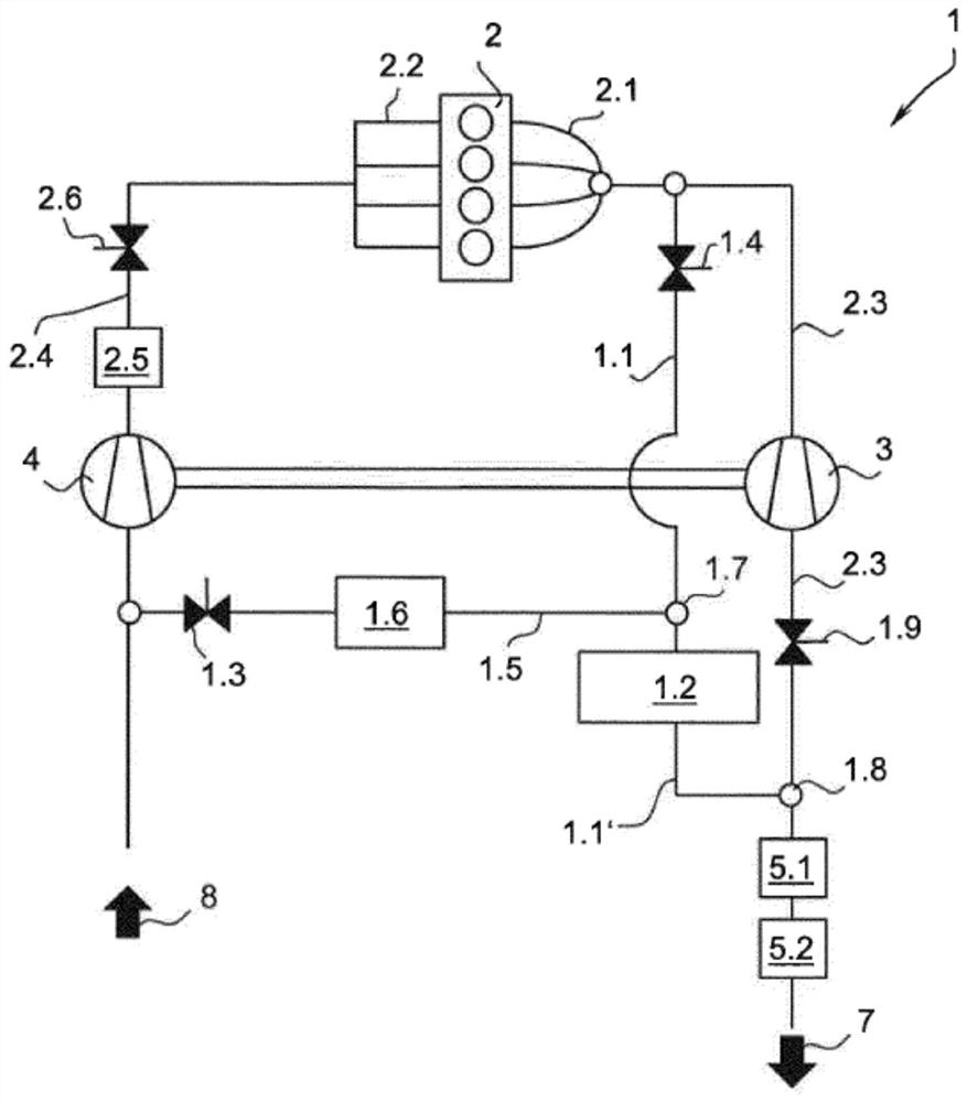
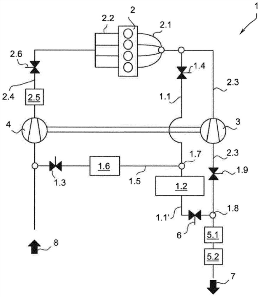
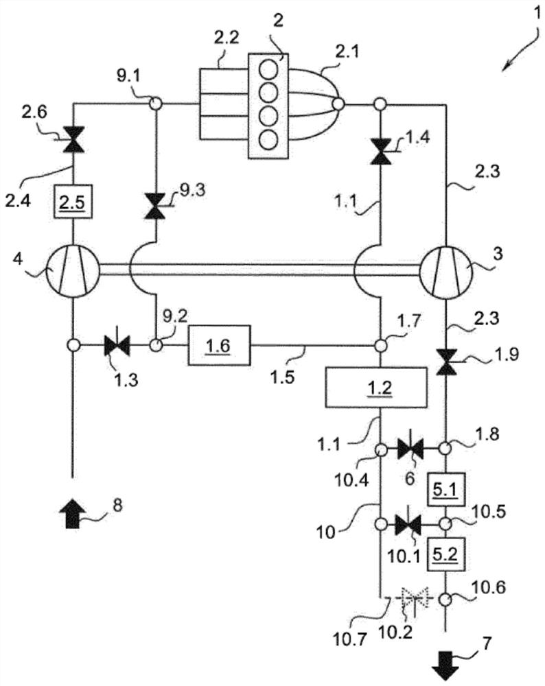
[0029] in accordance with figure 1In all schematic diagrams of the exemplary embodiment up to the figures, an exhaust gas conduction system 1 (EGR system) is disclosed which is integrated into a 3 and charge air compressor 4 in the exhaust gas and charge air system of the gasoline engine 2. The exhaust gas and charge air system has an exhaust gas line 2.3, which is connected to the exhaust manifold 2.1 of the gasoline engine 2, in which the turbine 3 is integrated. At the end of the exhaust gas line 2.3, the exhaust gas 7 leaves the exhaust system 1 and flows into an additional exhaust gas path, not shown. In addition, the present invention also provides an intake line 2.4, which is connected to the intake manifold 2.2 of the gasoline engine 2, in which the compressor 4 is integrated. The intake line 2.4 is supplied with fresh air 8 via an intake system not shown. In addition, the invention also provides a bypass line 1.1 which branches off from the exhaust line 2.3 and bra...


PUM


Abstract

The invention relates to an exhaust gas conduction system (1) for a gasoline engine (2), comprising an exhaust gas line (2.3) which can be connected to an exhaust manifold (2.1) of the gasoline engine(2), an intake line (2.4) which can be connected to an intake manifold (2.2) of the gasoline engine (2), a charge air compressor (4) which is arranged in the intake line (2.4), and a turbine (3) which is arranged in the exhaust gas line (2.3). The exhaust gas line (2.3) has at least one bypass line (1.1) with a bypass throttle valve (1.4), said line branching off from the exhaust gas line (2.3) upstream of the turbine (3) and branching back into the exhaust gas line (2.3) at an opening (1.8) downstream of the turbine (3). At least one exhaust gas recirculation line (1.5) with an EGR throttlevalve (1.3) is provided, said line opening into the intake line (2.4), wherein the exhaust gas recirculation line (1.5) branches off from the bypass line (1.1) at a branch (1.7), and the bypass throttle valve (1.4) is arranged upstream of the branch (1.7) of the exhaust gas recirculation line (1.5). At least one particle filter (1.2) is arranged in the bypass line (1.1) downstream of the branch (1.7) of the exhaust gas recirculation line (1.5), and an exhaust gas valve (1.9) is provided in the exhaust gas line (2.3) upstream of the opening (1.8) of the bypass line (1.1).

Description

technical field [0001] The invention relates to an exhaust gas conduction system for a gasoline engine comprising an exhaust line connectable to an exhaust manifold of said gasoline engine, an intake line connectable to an intake manifold of said gasoline engine , a charge air compressor arranged in the intake line and a turbine arranged in the exhaust line, wherein the exhaust line has at least one bypass line with a bypass throttle valve Road, the bypass line is branched from the exhaust line upstream of the turbine and branched back to the exhaust line at an opening downstream of the turbine; at least one exhaust gas recirculation line of the EGR throttle valve, said exhaust gas recirculation line leading to said intake line, wherein said exhaust gas recirculation line branches off from said bypass line at a branch; wherein The bypass throttle valve is arranged upstream of a branch of the exhaust gas recirculation line; wherein a waste gas valve is provided in the exhaust ...

Claims


Application Information

Patent Timeline
IPC IPC(8): F02B37/18F02M26/05F02M26/07F02M26/15F02M26/23F02M26/14F01N3/021F02M26/35F02M26/42F02M26/06F01N3/20F01N3/031
CPCF01N3/021F01N3/031F01N3/2053F02B37/18F02M26/05F02M26/06F02M26/07F02M26/15F02M26/23F02M26/35F02M26/42F01N3/035F01N13/009Y02T10/12F01N3/101F01N3/20F02B47/08
Inventor 菲利普·克鲁兹齐格迈克尔·费舍尔雅罗斯拉夫·基拉特
Owner TENNECO
Why Eureka
Try Eureka