
Deep cavity processing method

A processing method and deep cavity technology, applied in metal processing equipment, manufacturing tools, other manufacturing equipment/tools, etc., can solve problems such as easy broken knives, achieve the effects of less deviation, less processing time, and convenient positioning

Inactive Publication Date: 2020-10-13
ANHUI TATFOOK TECH CO LTD
View PDF8 Cites 1 Cited by
  • Summary
  • Abstract
  • Description
  • Claims
  • Application Information

AI Technical Summary

Problems solved by technology

[0005] Therefore, the technical problem to be solved by the present invention is to overcome the defect that the deep cavity in the prior art is easy to break when the deep cavity is processed layer by layer, thereby providing a deep cavity processing method

Method used


Image

  • Deep cavity processing method
  • Deep cavity processing method
  • Deep cavity processing method

Examples


Embodiment Construction

[0037] The technical solutions of the present invention will be clearly and completely described below in conjunction with the accompanying drawings. Apparently, the described embodiments are some of the embodiments of the present invention, but not all of them. Based on the embodiments of the present invention, all other embodiments obtained by persons of ordinary skill in the art without making creative efforts belong to the protection scope of the present invention.

[0038] In the description of the present invention, it should be noted that the terms "center", "upper", "lower", "left", "right", "vertical", "horizontal", "inner", "outer" etc. The indicated orientation or positional relationship is based on the orientation or positional relationship shown in the drawings, and is only for the convenience of describing the present invention and simplifying the description, rather than indicating or implying that the referred device or element must have a specific orientation, ...


PUM


Abstract

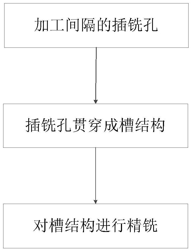
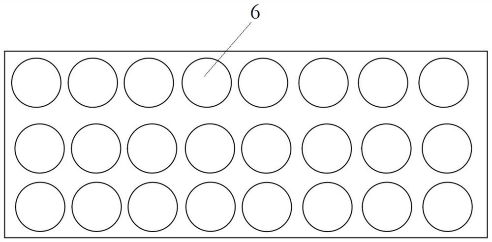
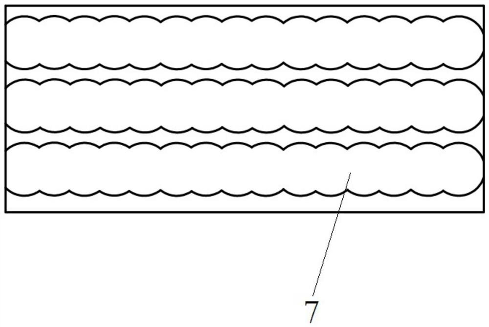
The invention provides a deep cavity processing method, and belongs to the technical field of machine tool processing. The deep cavity processing method comprises the following steps of step I, drilling a plurality of inserting milling holes having spacing on a workpiece in the processing direction of a deep cavity; step II, penetrating the inserting milling holes to form a groove structure through a milling cutter in the arraying direction of the inserting milling holes; and step III, performing finish milling on the side wall and the bottom wall of the groove structure through the milling cutter. Through the adoption of the deep cavity processing method disclosed by the invention, uneven stress of a cutter during deep processing process of the groove is avoided, the probability of cutterbreaking in the processing process is reduced, and abnormalities processing time is saved, i.e. the processing cycle is shortened.

Description

technical field [0001] The invention relates to the technical field of machine tool processing, in particular to a deep cavity processing method. Background technique [0002] A filter is a filter circuit composed of capacitors, inductors and resistors. There is a heat dissipation tooth structure in the cavity of the filter, the width of the heat dissipation tooth structure is 9-10mm, and the depth is 80-90mm. [0003] In the traditional processing method, an alloy milling cutter with a diameter of 8mm is used to process downward layer by layer in the depth direction, that is, the milling cutter first enters a certain depth along the Z direction, and cuts along the X direction along the depth to form a Shallow groove; based on the depth of the first time, enter a certain depth along the Z direction first, and cut along the X direction along this depth to form a deeper groove; repeat this cutting in turn until it reaches 80-90mm depth. [0004] However, due to the large de...

Claims


Application Information

Patent Timeline
Patent Type & Authority Applications(China)
IPC IPC(8): B23P23/02B23C3/00
CPCB23C3/00B23P23/02
Inventor 颜建金李嘉刘森林黄振华
Owner ANHUI TATFOOK TECH CO LTD
Learn More