Curved glass cutting device

A cutting device and curved glass technology, applied in glass cutting devices, glass manufacturing equipment, manufacturing tools, etc., can solve problems such as easy offset and glass cutting that does not meet specifications, and achieve the effect of improving cutting quality and improving cutting efficiency.

Inactive Publication Date: 2020-10-13
安徽蓝博玻璃有限公司
0 Cites 2 Cited by

AI-Extracted Technical Summary

Problems solved by technology

[0004] The purpose of the present invention is to provide a curved glass cutting device. By uniformly setting support columns on the operating table, the springs can be squeezed by the springs on the support columns so that the curved glass can closely fit t...

Abstract

The invention discloses a curved glass cutting device, and relates to the technical field of glass cutting. The device comprises an operation table, supporting columns and a portal frame. Guide railsare installed on the two sides of the operation table correspondingly. A limiting plate is arranged on one side of each guide rail; a screw rod is rotationally mounted between each limiting plate anda baffle plate; and the plurality of supporting columns are evenly installed on the operation table. Each supporting column comprises a fixed pipe fixed to the operation table. A suction pipe is sleeved in each fixed pipe; a sucker is fixed at the upper end of each suction pipe; a sucker is fixed at the upper ends of the suction pipes; the bottom ends of two vertical rods of the portal frame are slidably mounted on the guide rails; a sliding rod is sleeved with a sliding block; and a cutter is fixed on a telescopic rod below the sliding block. The supporting columns are uniformly arranged on the operation table, springs arranged on the supporting columns in a sleeving mode are used for enabling spring curved glass to be tightly attached to the bottom face of the glass under extrusion of the spring curved glass, meanwhile, the cutter on the portal frame above completes cutting of the curved glass, the glass cannot move when a user cuts the glass, and the cutting quality and the cuttingefficiency of the curved glass are improved.

Application Domain

Glass severing apparatus

Technology Topic

Portal frame

Image

  • Curved glass cutting device
  • Curved glass cutting device
  • Curved glass cutting device

Examples

  • Experimental program(1)

Example Embodiment

[0029] The technical solutions in the embodiments of the present invention will be clearly and completely described below in conjunction with the accompanying drawings in the embodiments of the present invention. Obviously, the described embodiments are only a part of the embodiments of the present invention, rather than all the embodiments. Based on the embodiments of the present invention, all other embodiments obtained by those of ordinary skill in the art without creative work shall fall within the protection scope of the present invention.
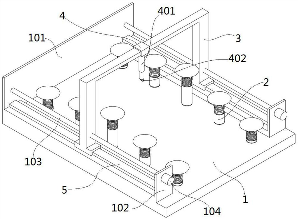
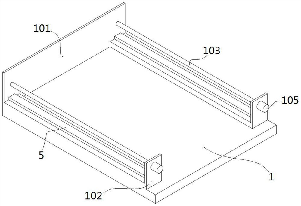
[0030] See Figure 1-7 As shown, the present invention is a curved glass cutting device, including an operating table 1, a supporting column 2, a gantry 3,
[0031] There is a baffle 101 on one side of the operation table 1; a guide rail 5 is installed on both sides of the operation table 1; a limit plate 102 is installed on one side of the guide rail 5; a screw 103 is rotatably installed between the limit plate 102 and the baffle 101; A number of support columns 2 are evenly installed on 1; the support columns 2 are installed between the two guide rails 5;
[0032] The support column 2 includes a fixed tube 201 fixed on the operating table 1; a suction tube 202 is sleeved in the fixed tube 201; a suction cup 203 is fixed on the upper end of the suction tube 202; a spring 204 is sleeved on the suction tube 202; both ends of the spring 204 are connected to the fixed tube respectively The upper edge of 201 and the lower edge of the suction cup 203 are fixedly connected;
[0033] The gantry 3 includes a sliding rod 301 and vertical rods 302 vertically arranged at both ends of the sliding rod 301; the bottom ends of the two vertical rods 302 are slidably mounted on the guide rail 5; the sliding rod 301 is sleeved with a sliding block 4; the lower surface of the sliding block 4 A telescopic rod 401 is provided; a cutter 402 is fixed at the lower end of the telescopic rod 401.
[0034] Among them, one end of the two guide rails 5 is fixed to the baffle 101 and the guide rails are perpendicular to the baffle 101.
[0035] Among them, the screw 103 is located above the guide rail 5 and is arranged parallel to the guide rail 5; one end of the screw 103 passes through the limit plate 102 and is connected to the output shaft of the motor 104 installed on the side of the limit plate 102. The synchronous rotation of the two motors 104 can enable The screw 103 rotates accordingly, and the rotation of the screw 103 allows the gantry 3 to move back and forth at a uniform speed.
[0036] Wherein, the vertical rod 302 is provided with a screw hole; the screw 103 passes through the vertical rod 302 and cooperates with the screw 103.
[0037] The lower end of the vertical rod 302 is provided with a rim-shaped slider 303; the guide rail 5 is a convex plate; the rim-shaped slider 303 is slidably clamped on the convex plate.
[0038] Among them, the lower end of the suction tube 203 passes through the console 1 and communicates with the vacuum generator installed under the console 1. The support column 2 is at the same height when the suction cup 204 is not under heavy pressure. When the curved glass is placed on the support column 2, it supports The column 2 will make the supporting column 2 fit the curved glass under the gravity of the curved glass, so that all the suction cups 204 can fit the curved glass, and the vacuum generator is connected to the suction pipe 203 to complete the fixing of the curved glass, which is convenient for the user to cut the glass.

PUM

no PUM

Description & Claims & Application Information

We can also present the details of the Description, Claims and Application information to help users get a comprehensive understanding of the technical details of the patent, such as background art, summary of invention, brief description of drawings, description of embodiments, and other original content. On the other hand, users can also determine the specific scope of protection of the technology through the list of claims; as well as understand the changes in the life cycle of the technology with the presentation of the patent timeline. Login to view more.

Similar technology patents

Cutting machine with positioning and guiding structure for scaffold fastener production

ActiveCN112620814AEasy orientation and positioningImprove cut quality
Owner:安徽华友工程设备有限责任公司

Automatic cutting robot for PVC pipe

ActiveCN106272710AImprove cut qualityfast cutting speed
Owner:创一新材料(重庆)有限公司

Shearing machine and locating device of bearing panel thereof

ActiveCN104907624AReduce maintenance frequencyImprove cut quality
Owner:SHANDONG IRON & STEEL CO LTD

Intelligent electronic equipment cutting device

InactiveCN107900458AImprove cut qualitysave energy
Owner:成都弘硅科技有限公司

Cutting process method of quartz wafer

PendingCN114274384AResolves edge effects and asymmetric cutting trajectory offsetsImprove cut quality
Owner:TANGSHAN GUOXIN JINGYUAN ELECTRONICS CO LTD

Classification and recommendation of technical efficacy words

  • Improve cutting efficiency
  • Improve cut quality

Automatic feeding and discharging laser cutting machine

ActiveCN102500931AShort loading and unloading timeImprove cutting efficiency
Owner:SHENZHEN GDLASER TECH CO LTD

Large water cutting equipment for steel

Owner:佛山市德法科技有限公司

Circumferential cutting machine for circular tube

ActiveCN104907626AImprove cutting efficiencycut surface smooth
Owner:ZHUJI JIAERDA MACHINERY

Manual multi-knife lens cutter

InactiveCN101734848AImprove cutting efficiencyHigh accuracy of billet size
Owner:常州金坛康达克光电科技有限公司

Multi-line silicon wafer cutting method

ActiveCN103192462AReduce adverse effects of cuttingImprove cut quality
Owner:TIANJIN YINGLI NEW ENERGY RESOURCES

Large-diameter long-pipe-fitting pipe-end cutting device

ActiveCN103341679AImprove cut qualityReduced post-grinding work
Owner:CHINA NAT OFFSHORE OIL CORP +3

Pipe pressing cutting device for cutting PVC pipe

InactiveCN103213153AImprove cut quality
Owner:张家港市金远东机械有限公司

Hub type diamond ultra-thin cutting sheet for PCB and application thereof

ActiveCN109623676AImprove sharpnessImprove cut quality
Owner:赛尔科技(如东)有限公司

Spherical knife-type self-propelled tea picker for famous tea

ActiveCN111713257AImprove stabilityImprove cut quality
Owner:ZHEJIANG SCI-TECH UNIV
Why Eureka
Try Eureka