Electric connector plugging mechanism

A technology of plug-in mechanism and electrical connector, which is applied in the field of power station, can solve the problems that the power battery cannot be connected, waste the user's physical strength, prolong the charging time of the power battery, etc., and achieve the effect of improving charging efficiency, realizing charging, and shortening the charging time

Active Publication Date: 2020-10-13
蓝谷智慧(北京)能源科技有限公司
View PDF11 Cites 4 Cited by
  • Summary
  • Abstract
  • Description
  • Claims
  • Application Information

AI Technical Summary

Problems solved by technology

[0003] However, the user needs to manually connect the power battery to the electrical connection device to charge the power battery. The power battery cannot be connected to the electrical connection device quickly and accurately, resulting in prolonged charging time of the power battery, thereby affecting the charging efficiency of the power battery, and , will also waste the user's energy

Method used


Image

  • Electric connector plugging mechanism
  • Electric connector plugging mechanism
  • Electric connector plugging mechanism

Examples


Embodiment Construction

[0031] Embodiments of the present invention are described in detail below, examples of which are shown in the drawings, wherein the same or similar reference numerals designate the same or similar elements or elements having the same or similar functions throughout. The embodiments described below by referring to the figures are exemplary only for explaining the present invention and should not be construed as limiting the present invention.

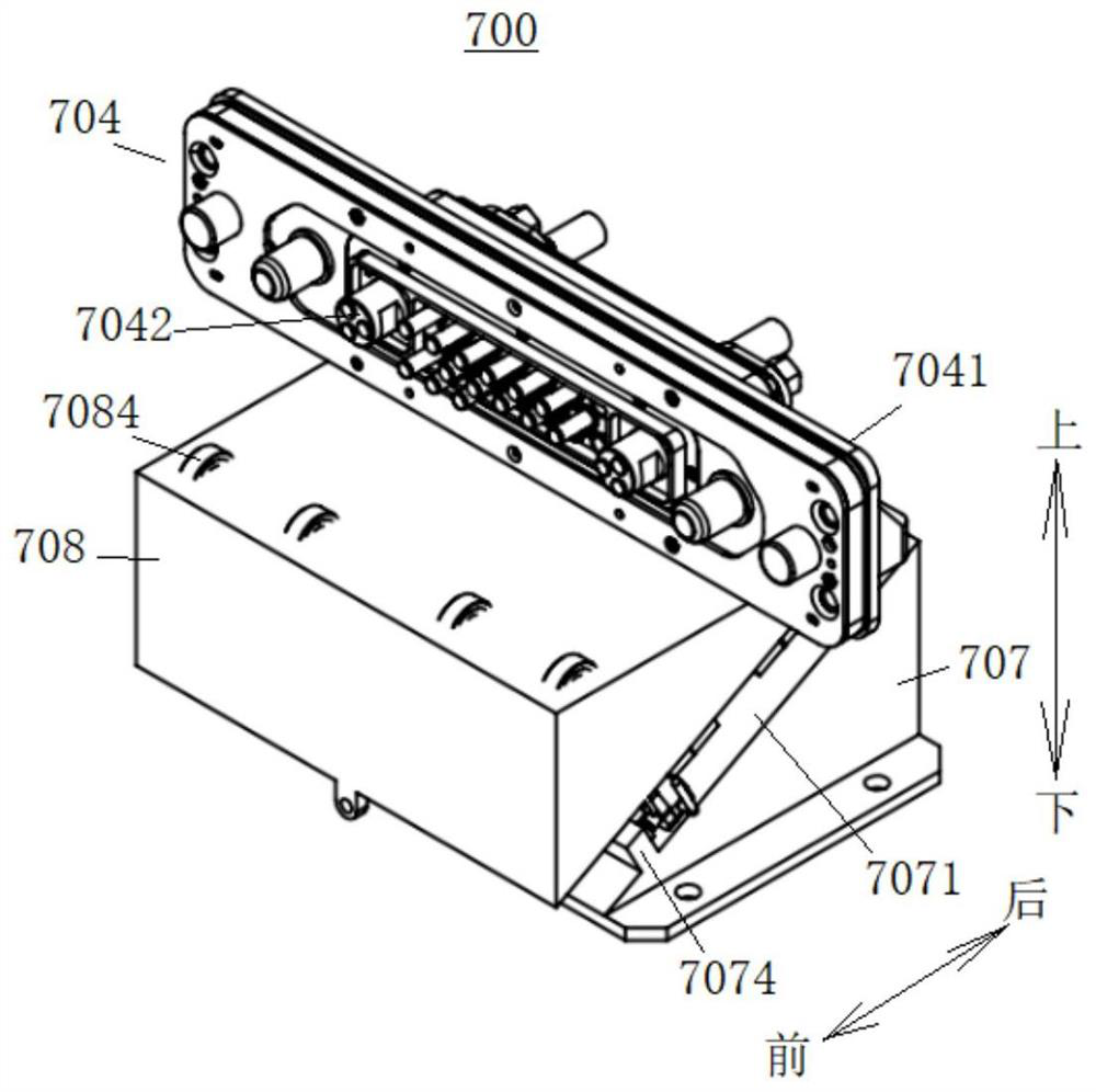
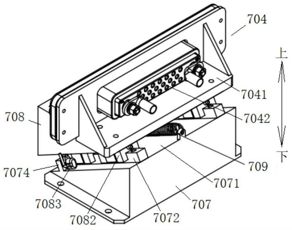
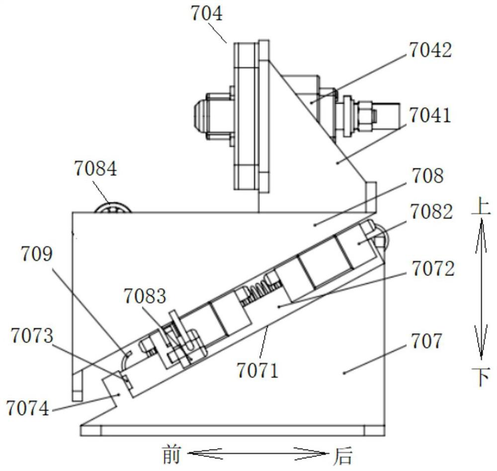
[0032] Refer below Figure 1-Figure 5 The electric connector plugging mechanism 700 according to the embodiment of the present invention is described.

[0033] Such as Figure 1-Figure 5 As shown, the electrical connector plugging mechanism 700 according to the embodiment of the present invention includes: a lower wedge 707 , an upper wedge 708 and an electrical connection device 704 . The lower wedge 707 has a first slope 7071 , preferably, the upper surface of the lower wedge 707 is set as the first slope 7071 , and the upper wedge 7...


PUM


Abstract

The invention discloses an electric connector plugging mechanism comprising a lower wedge block which is provided with a first inclined plane, an upper wedge block arranged on the first inclined surface in a sliding manner and an electric connecting device which is fixedly arranged on the upper wedge block. The upper wedge block slides towards the bottom end of the lower wedge block along the first inclined surface under the action of external force, so that the electric connecting device is in butt joint with the battery pack. Therefore, through the cooperation of the lower wedge block, the upper wedge block and the electric connecting device, the battery pack and the electric connecting device can be quickly and accurately butted together, and the charging time of the battery pack can beshortened, so that the charging efficiency of the battery pack can be improved, and the working purpose of automatically charging the battery pack can also be achieved.

Description

technical field [0001] The invention relates to the field of substations, in particular to an electrical connector plug-in mechanism. Background technique [0002] In the related technology, the electric vehicle is driven into the power exchange station to replace the power battery. After the power battery is disassembled from the vehicle body, the power battery is placed on the battery rack in the power exchange station, and the power battery is charged on the battery rack. [0003] However, the user needs to manually connect the power battery to the electrical connection device to charge the power battery. The power battery cannot be connected to the electrical connection device quickly and accurately, resulting in prolonged charging time of the power battery, thereby affecting the charging efficiency of the power battery, and , will also waste the user's energy. Contents of the invention [0004] The present invention aims to solve at least one of the technical problem...

Claims


Application Information

Patent Timeline
Patent Type & Authority Applications(China)
IPC IPC(8): H01R13/629H01M2/20B60L53/80
CPCB60L53/80H01R13/629H01R2201/26Y02T10/70Y02T10/7072
Inventor 王亚光
Owner 蓝谷智慧(北京)能源科技有限公司
Why Eureka
Try Eureka